1. Installation
SAFETY PRECAUTIONS
- This equipment must be installed and operated by suitably authorized and qualified personnel only.
- Please follow appropriate safety procedures and when installing this equipment.
- Ensure all external cables leading to this equipment are adequately protected and correctly installed according to local regulatory requirements.
- Ensure that this equipment is installed correctly as detailed in this manual.
GENERAL PRECAUTIONS/NOTICES
- Except where approved by LoadScan Ltd or its agents, do not attempt to service, disassemble, repair or modify any CVS components yourself. Unauthorized repairs or modifications may void the manufacturer’s warranty.
- LoadScan Ltd shall not be responsible for any damage attributable to incorrect installation, operation or handling of this equipment or improper operating environments which are not suitable for this equipment.
- This device may include a wireless (WiFi) RF transmitter module that operates in either the 2.4 GHz or 5 GHz license-free radio spectrum. The FCC ID for this transmitter module, if fitted, can be found on the main information label for this device.
- This device contains a Class I (eye-safe) laser component. The FDA ID for this component can be found on the main information label for this device.
Disclaimer
The information in this document is subject to change without notice. While the information contained herein is assumed to be accurate at time of writing, LoadScan Ltd assumes no responsibility for errors or omissions.
Trademarks
Products and company names listed in this document are recognized as trademarks or trade names of their respective companies.
Revision 3.0, September 2020
Copyright © 2020 LoadScan Ltd. All rights reserved.
- This manual and other supporting documents referenced in this manual can be viewed/downloaded from the Help page accessible from the CVS web user-interface menu.
- This equipment must be installed by suitably qualified personnel with electrical installation and Information Technology (IT) knowledge and experience.
- Please follow electrical and safety regulations and site requirements when installing this equipment.
- Do not open the CVS scan head unit.
1.1 Preparation
1.1.1 System components
Check all supplied components before proceeding with installation.
Standard components:
 |
CVS scan head (installed inside frame center section for shipping) |
 |
CVS-1PS Waterproof flange-mount AC-DC power supply with 5 m (16.4 ft) DC power cable and connector (output side) |
 |
Mounting frame sections, brackets, and fasteners | 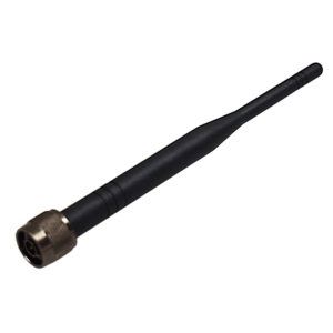 |
Dual band (2.4 GHz / 5 GHz) wireless antenna |
 |
Sealing glands (2) for optional LAN and I/O wired Ethernet connectors (fitted to CVS scan head for sealing) |
 |
Speed sensor mounting bracket and sensor target bolt/bracket |
 |
Inductive speed sensor | 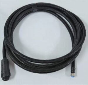 |
Speed sensor cable, 5m (16.4 ft) |
Optional extension cables:
 |
DC power extension cable, 15m (49.2 ft) |
 |
Speed sensor extension cable, 10m (32.8 ft) or 20m (65.6 ft) |
Add-on I/O components:
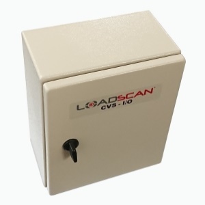 |
CVS-I/O enclosure |  |
CVS-I/O power and communications combo cable, 3m (16.4 ft) |
 |
CVS-I/O frame-mounting brackets |  |
[Optional]
For remote CVS-I/O installation only. CVS-1PS Waterproof flange-mount AC-DC power supply, 5 m (9.8 ft) DC power cable |
1.1.2 Prepare the frame
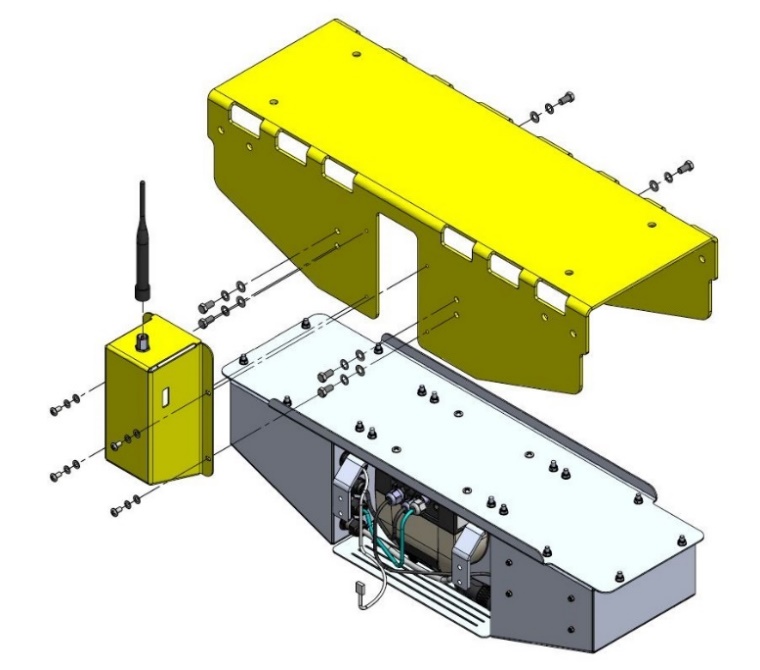
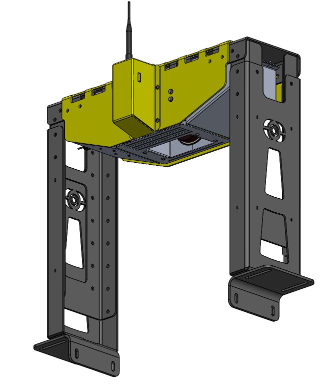
Detach the external WiFi cover from the frame center section and then remove the CVS scan head from the frame center section and place aside in a safe location with laser window facing downwards for protection. The scan head is removed to make frame assembly easier and protect it from damage during frame assembly. It will be re-installed after the frame is fully assembled on the conveyor. The exploded view below shows the location of all screws that must be removed to detach the WiFi cover and slide the scan head out of the frame center section.
1.2 Mounting the CVS
Refer to LoadScan CVS Frame Assembly Drawings document for detailed assembly drawings.
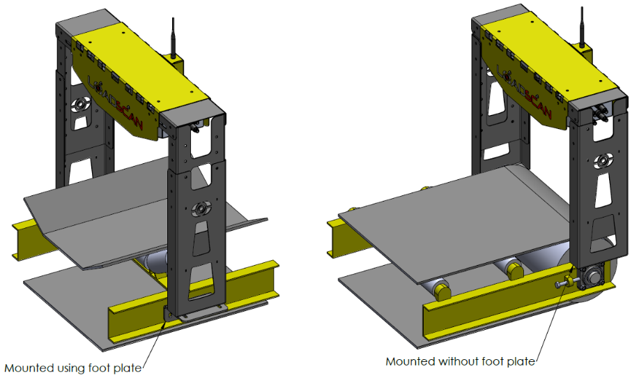
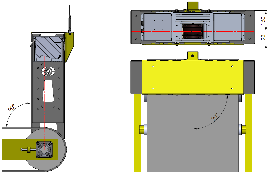
1.2.1 Mount the frame
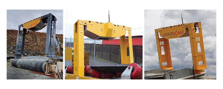
- Laser window as close as possible to drive roller or support roller (laser beam over roller)
- Frame centered over belt and securely fastened to conveyor support structure
- Frame perpendicular to belt angle of elevation and travel direction
- Area between belt and frame clear
Notes
- The preferred location is over the drive roller. If this not possible then the CVS may be mounted over a support roller/idler set. In this case, ensure that the belt is firmly in contact with the roller(s), even when there is no material on the belt and does not move significantly from side to side or flex (alter profile) under different loading conditions. Accuracy may be reduced if CVS not mounted over an end roller.
- Avoid mounting location subject to high vibration or shock.
- The frame may be installed in either orientation across the belt. Note how this affects the relative position of the laser window and the location of the cable connectors before selecting mounting location and orientation.
- See 5 Technical Specifications for frame dimensional drawings with extension ranges for each size.
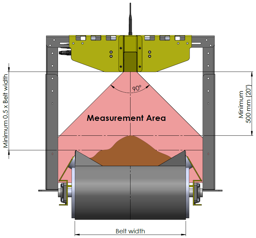
1.2.2 Set frame height
- Minimum 500 mm (20”) from highest point on loaded belt to bottom edge of frame (under typical maximum load conditions)
- Minimum 0.5 x belt width above belt edges to bottom edge of frame
- Extra safety margin for clearance of large rocks/lumps if required
1.2.3 Install CVS scan head
Insert the CVS scan head into the frame center section and re-attach the WiFi cover in the reverse order from step 1.1.2. Ensure all previously removed screws are re-used and firmly tightened.
1.3 Installing the Speed Sensor
Refer to LoadScan CVS Speed Sensor Mounting Drawings document for detailed mounting drawings.
1.3.1 Mount sensor and target
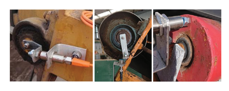
The inductive speed sensor allows measurement of belt speed by detecting revolutions of the belt drive roller. Mount the sensor and target by one of the methods illustrated in the images below or examples in LoadScan CVS Speed Sensor Mounting Drawings. A suitable steel detection target must be affixed to the drive roller and aligned with the inductive sensor so that the target passes the sensor once per revolution, with a gap of 3-5 mm (0.12-0.2”) between the sensor and target when the target passes the sensor.
Notes
- The time between inductive sensor pulses must be less than 2.5 seconds. At a lower pulse rate, the reported belt speed will be zero.
- The CVS is supplied with an aluminium bracket that can be folded, cut and drilled as required to mount the inductive speed sensor as well as a steel bolt (sensor target) fitted to an aluminium bracket that can be folded, cut and drilled for center-mounting on the drive roller shaft.
- Standard supplied speed sensor cable is 5 m. An extension is required if the sensor needs to be more than 5 m from the CVS unit.
- If the belt has a known fixed speed, then a speed sensor is optional. However, a speed sensor is suggested unless the belt speed is regulated by a motor speed controller and this does not vary under different loading conditions or electric or hydraulic power conditions.
1.3.2 Measure drive roller circumference
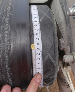
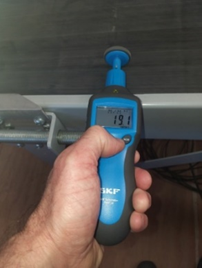
Accurately measure and record the circumference of the drive roller (in mm) for speed calibration. Alternatively, a hand-held tachometer fitted with a wheel can be used for belt speed calibration. See 2.3.3 Belt speed for belt speed input method and calibration settings.
1.4 Electrical Connections
1.4.1 Cable connectors
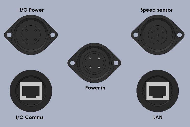
Notes
- To maintain weather-proof sealing of the CVS, please leave sealing caps/glands on all unused cable connectors.
- Ensure all external cables leading to this equipment are adequately protected and correctly installed according to local regulatory requirements.
1.4.2 Power
CVS power requirements are 9-36VDC, 3A max. @ 24 VDC with heater off, 6A max. @ 24 VDC with heater on (at start-up below 5°C/41°F). Power input is via an Amphenol Ecomate® (C16-1 series) 4-pin male panel connector.
| Pin | Signal | Description |
|---|---|---|
| 1 | +VDC | Positive DC supply input |
| 2 | -VDC | Negative DC supply input |
| 3 | Unused | |
| 4 (Earth) | Earth | Earth connection to chassis |
 The CVS is supplied with a CVS-1PS waterproof AC-DC power supply which can power the CVS from 90-305 VAC mains power. This can be installed directly on the frame of the conveyor if an electrical cabinet is not available and is supplied with 5m (16.4’) of DC power cable and connector. Waterproof connectors must be used for AC input wiring if mounted externally. An optional 15m (49.2 ft) DC power extension cable can extend the distance to power supply. DC power cables can be cut, or Amphenol connectors re-wired for direct connection to a 12/24 VDC power source. Install power connections according to local electrical regulations and site requirements.
1.4.3 Speed sensor
Speed sensor input is via an Amphenol Ecomate® (C16-1 series) 7-pin female panel connector. The CVS is supplied with a standard 5m speed sensor cable, with optional extension cable available. Connect the cable between the inductive speed sensor and the CVS scan head.
| Pin | Signal | Description |
|---|---|---|
| 1 | +24VDC OUT | Sensor power supply positive output |
| 2 | -24VDC OUT | Sensor power supply negative output |
| 3 | PULSE + | Sensor pulse signal positive input |
| 4 | Reserved | Special function input |
| 5 | PULSE – | Sensor pulse signal negative input |
| 6 | Unused | |
| 7 (Earth) | SHIELD | Cable Shield (chassis Earth) |
1.4.4 Wired Ethernet (LAN)
Optional wired Ethernet connection is provided by a waterproof RJ-45 panel jack. This is supplied with a mating cable gland for sealing standard RJ-45 terminated Ethernet cable.
1.4.5 I/O
The CVS scan head has connectors for an optional CVS-I/O box which provides analogue and digital inputs and outputs for direct connection to PLCs and other control and monitoring devices. The CVS-I/O box is an external add-on for the CVS. It can be installed locally on the CVS mounting frame and is supplied with a 3m combo cable for connection to the CVS scan head. It can also be installed remotely, closer to control and monitoring equipment if required. In this case the user is responsible for installing Ethernet cabling for communication between the CVS scan head and the CVS-I/O box and providing power to the box.
Refer to LoadScan CVS-I/O Installation Guide document for installation and signal wiring diagrams.
The I/O power connector on the CVS scan head is an Amphenol Ecomate® (C16-1 series) 7-pin female panel connector and provides 24 VDC power output. This connector and the mating male connector on the CVS-I/O box have the same pin-out as described in 1.4.2 Power, above.
The I/O Comms connector is a waterproof RJ-45 panel jack. This is supplied with a mating cable gland for sealing standard RJ-45 terminated Ethernet cable. The same connector is used on the CVS-I/O box.
If the CVS-I/O box is not connected to the CVS scan head via supplied 3m combo cable, then an external power source (12 – 30 VDC) must be used. LoadScan can supply an additional CVS-1PS waterproof 24 VDC power supply for this purpose (see 1.4.2 Power, above).
See 2.4 Input/Output Configuration for CVS measurement value, status signal, control value and control signal mapping options for analogue and digital inputs and outputs.
Important Notes
- 24 VDC power output from the CVS scan head must be used for CVS-I/O only. Connection to other devices may void the manufacturer warranty.
- If the CVS-I/O box is installed away from the CVS then the communication link between the box and the CVS must be via a direct, dedicated Ethernet wired or fibre link and not part of a network. A wired Ethernet cable link should not exceed 100m and should have no intermediate joins.
In this Article
1. Installation
SAFETY PRECAUTIONS
- This equipment must be installed and operated by suitably authorized and qualified personnel only.
- Please follow appropriate safety procedures and when installing this equipment.
- Ensure all external cables leading to this equipment are adequately protected and correctly installed according to local regulatory requirements.
- Ensure that this equipment is installed correctly as detailed in this manual.
GENERAL PRECAUTIONS/NOTICES
- Except where approved by LoadScan Ltd or its agents, do not attempt to service, disassemble, repair or modify any CVS components yourself. Unauthorized repairs or modifications may void the manufacturer’s warranty.
- LoadScan Ltd shall not be responsible for any damage attributable to incorrect installation, operation or handling of this equipment or improper operating environments which are not suitable for this equipment.
- This device may include a wireless (WiFi) RF transmitter module that operates in either the 2.4 GHz or 5 GHz license-free radio spectrum. The FCC ID for this transmitter module, if fitted, can be found on the main information label for this device.
- This device contains a Class I (eye-safe) laser component. The FDA ID for this component can be found on the main information label for this device.
Disclaimer
The information in this document is subject to change without notice. While the information contained herein is assumed to be accurate at time of writing, LoadScan Ltd assumes no responsibility for errors or omissions.
Trademarks
Products and company names listed in this document are recognized as trademarks or trade names of their respective companies.
Revision 3.0, September 2020
Copyright © 2020 LoadScan Ltd. All rights reserved.
- This manual and other supporting documents referenced in this manual can be viewed/downloaded from the Help page accessible from the CVS web user-interface menu.
- This equipment must be installed by suitably qualified personnel with electrical installation and Information Technology (IT) knowledge and experience.
- Please follow electrical and safety regulations and site requirements when installing this equipment.
- Do not open the CVS scan head unit.
1.1 Preparation
1.1.1 System components
Check all supplied components before proceeding with installation.
Standard components:
 |
CVS scan head (installed inside frame center section for shipping) |
 |
CVS-1PS Waterproof flange-mount AC-DC power supply with 5 m (16.4 ft) DC power cable and connector (output side) |
 |
Mounting frame sections, brackets, and fasteners |  |
Dual band (2.4 GHz / 5 GHz) wireless antenna |
 |
Sealing glands (2) for optional LAN and I/O wired Ethernet connectors (fitted to CVS scan head for sealing) |
 |
Speed sensor mounting bracket and sensor target bolt/bracket |
 |
Inductive speed sensor |  |
Speed sensor cable, 5m (16.4 ft) |
Optional extension cables:
 |
DC power extension cable, 15m (49.2 ft) |
 |
Speed sensor extension cable, 10m (32.8 ft) or 20m (65.6 ft) |
Add-on I/O components:
 |
CVS-I/O enclosure |  |
CVS-I/O power and communications combo cable, 3m (16.4 ft) |
 |
CVS-I/O frame-mounting brackets |  |
[Optional]
For remote CVS-I/O installation only. CVS-1PS Waterproof flange-mount AC-DC power supply, 5 m (9.8 ft) DC power cable |
1.1.2 Prepare the frame
Detach the external WiFi cover from the frame center section and then remove the CVS scan head from the frame center section and place aside in a safe location with laser window facing downwards for protection. The scan head is removed to make frame assembly easier and protect it from damage during frame assembly. It will be re-installed after the frame is fully assembled on the conveyor. The exploded view below shows the location of all screws that must be removed to detach the WiFi cover and slide the scan head out of the frame center section.

1.2 Mounting the CVS
Refer to LoadScan CVS Frame Assembly Drawings document for detailed assembly drawings.
1.2.1 Mount the frame
- Laser window as close as possible to drive roller or support roller (laser beam over roller)
- Frame centered over belt and securely fastened to conveyor support structure
- Frame perpendicular to belt angle of elevation and travel direction
- Area between belt and frame clear


Notes
- The preferred location is over the drive roller. If this not possible then the CVS may be mounted over a support roller/idler set. In this case, ensure that the belt is firmly in contact with the roller(s), even when there is no material on the belt and does not move significantly from side to side or flex (alter profile) under different loading conditions. Accuracy may be reduced if CVS not mounted over an end roller.
- Avoid mounting location subject to high vibration or shock.
- The frame may be installed in either orientation across the belt. Note how this affects the relative position of the laser window and the location of the cable connectors before selecting mounting location and orientation.
- See 5 Technical Specifications for frame dimensional drawings with extension ranges for each size.
1.2.2 Set frame height
- Minimum 500 mm (20”) from highest point on loaded belt to bottom edge of frame (under typical maximum load conditions)
- Minimum 0.5 x belt width above belt edges to bottom edge of frame
- Extra safety margin for clearance of large rocks/lumps if required

1.2.3 Install CVS scan head
Insert the CVS scan head into the frame center section and re-attach the WiFi cover in the reverse order from step 1.1.2. Ensure all previously removed screws are re-used and firmly tightened.


1.3 Installing the Speed Sensor
Refer to LoadScan CVS Speed Sensor Mounting Drawings document for detailed mounting drawings.
1.3.1 Mount sensor and target
The inductive speed sensor allows measurement of belt speed by detecting revolutions of the belt drive roller. Mount the sensor and target by one of the methods illustrated in the images below or examples in LoadScan CVS Speed Sensor Mounting Drawings. A suitable steel detection target must be affixed to the drive roller and aligned with the inductive sensor so that the target passes the sensor once per revolution, with a gap of 3-5 mm (0.12-0.2”) between the sensor and target when the target passes the sensor.

Notes
- The time between inductive sensor pulses must be less than 2.5 seconds. At a lower pulse rate, the reported belt speed will be zero.
- The CVS is supplied with an aluminium bracket that can be folded, cut and drilled as required to mount the inductive speed sensor as well as a steel bolt (sensor target) fitted to an aluminium bracket that can be folded, cut and drilled for center-mounting on the drive roller shaft.
- Standard supplied speed sensor cable is 5 m. An extension is required if the sensor needs to be more than 5 m from the CVS unit.
- If the belt has a known fixed speed, then a speed sensor is optional. However, a speed sensor is suggested unless the belt speed is regulated by a motor speed controller and this does not vary under different loading conditions or electric or hydraulic power conditions.
1.3.2 Measure drive roller circumference
Accurately measure and record the circumference of the drive roller (in mm) for speed calibration. Alternatively, a hand-held tachometer fitted with a wheel can be used for belt speed calibration. See 2.3.3 Belt speed for belt speed input method and calibration settings.


1.4 Electrical Connections
1.4.1 Cable connectors

Notes
- To maintain weather-proof sealing of the CVS, please leave sealing caps/glands on all unused cable connectors.
- Ensure all external cables leading to this equipment are adequately protected and correctly installed according to local regulatory requirements.
1.4.2 Power
CVS power requirements are 9-36VDC, 3A max. @ 24 VDC with heater off, 6A max. @ 24 VDC with heater on (at start-up below 5°C/41°F). Power input is via an Amphenol Ecomate® (C16-1 series) 4-pin male panel connector.
| Pin | Signal | Description |
|---|---|---|
| 1 | +VDC | Positive DC supply input |
| 2 | -VDC | Negative DC supply input |
| 3 | Unused | |
| 4 (Earth) | Earth | Earth connection to chassis |
 The CVS is supplied with a CVS-1PS waterproof AC-DC power supply which can power the CVS from 90-305 VAC mains power. This can be installed directly on the frame of the conveyor if an electrical cabinet is not available and is supplied with 5m (16.4’) of DC power cable and connector. Waterproof connectors must be used for AC input wiring if mounted externally. An optional 15m (49.2 ft) DC power extension cable can extend the distance to power supply. DC power cables can be cut, or Amphenol connectors re-wired for direct connection to a 12/24 VDC power source. Install power connections according to local electrical regulations and site requirements.
1.4.3 Speed sensor
Speed sensor input is via an Amphenol Ecomate® (C16-1 series) 7-pin female panel connector. The CVS is supplied with a standard 5m speed sensor cable, with optional extension cable available. Connect the cable between the inductive speed sensor and the CVS scan head.
| Pin | Signal | Description |
|---|---|---|
| 1 | +24VDC OUT | Sensor power supply positive output |
| 2 | -24VDC OUT | Sensor power supply negative output |
| 3 | PULSE + | Sensor pulse signal positive input |
| 4 | Reserved | Special function input |
| 5 | PULSE – | Sensor pulse signal negative input |
| 6 | Unused | |
| 7 (Earth) | SHIELD | Cable Shield (chassis Earth) |
1.4.4 Wired Ethernet (LAN)
Optional wired Ethernet connection is provided by a waterproof RJ-45 panel jack. This is supplied with a mating cable gland for sealing standard RJ-45 terminated Ethernet cable.
1.4.5 I/O
The CVS scan head has connectors for an optional CVS-I/O box which provides analogue and digital inputs and outputs for direct connection to PLCs and other control and monitoring devices. The CVS-I/O box is an external add-on for the CVS. It can be installed locally on the CVS mounting frame and is supplied with a 3m combo cable for connection to the CVS scan head. It can also be installed remotely, closer to control and monitoring equipment if required. In this case the user is responsible for installing Ethernet cabling for communication between the CVS scan head and the CVS-I/O box and providing power to the box.
Refer to LoadScan CVS-I/O Installation Guide document for installation and signal wiring diagrams.
The I/O power connector on the CVS scan head is an Amphenol Ecomate® (C16-1 series) 7-pin female panel connector and provides 24 VDC power output. This connector and the mating male connector on the CVS-I/O box have the same pin-out as described in 1.4.2 Power, above.
The I/O Comms connector is a waterproof RJ-45 panel jack. This is supplied with a mating cable gland for sealing standard RJ-45 terminated Ethernet cable. The same connector is used on the CVS-I/O box.
If the CVS-I/O box is not connected to the CVS scan head via supplied 3m combo cable, then an external power source (12 – 30 VDC) must be used. LoadScan can supply an additional CVS-1PS waterproof 24 VDC power supply for this purpose (see 1.4.2 Power, above).
See 2.4 Input/Output Configuration for CVS measurement value, status signal, control value and control signal mapping options for analogue and digital inputs and outputs.
Important Notes
- 24 VDC power output from the CVS scan head must be used for CVS-I/O only. Connection to other devices may void the manufacturer warranty.
- If the CVS-I/O box is installed away from the CVS then the communication link between the box and the CVS must be via a direct, dedicated Ethernet wired or fibre link and not part of a network. A wired Ethernet cable link should not exceed 100m and should have no intermediate joins.
