Introduction
The Load Volume Scanner (LVS) scan area is where the LVS looks for trucks.
Trucks must be completely within the scan area during scanning and anything outside this area will be ignored.
The scan area is defined by settings normally set by Loadscan technical staff at the time of initial installation.
In some cases, the scan area limits may need to be adjusted for different installation sites or different truck types.
This document explains the scan area settings and how to adjust them.
The scan area
Scan area limits should be adjusted only if advised by Loadscan technical support. They cannot be adjusted by end-users on trade certified LVS systems.
The scan area is defined by limit settings as shown below.
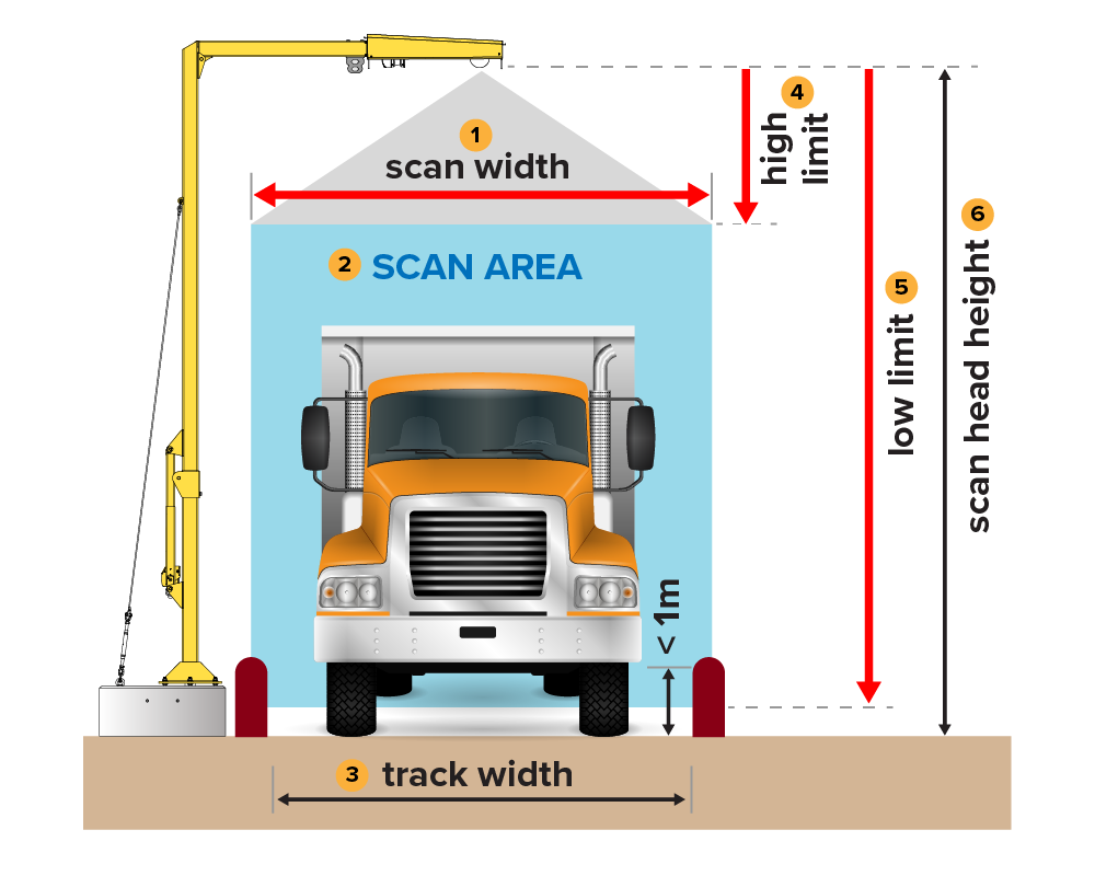
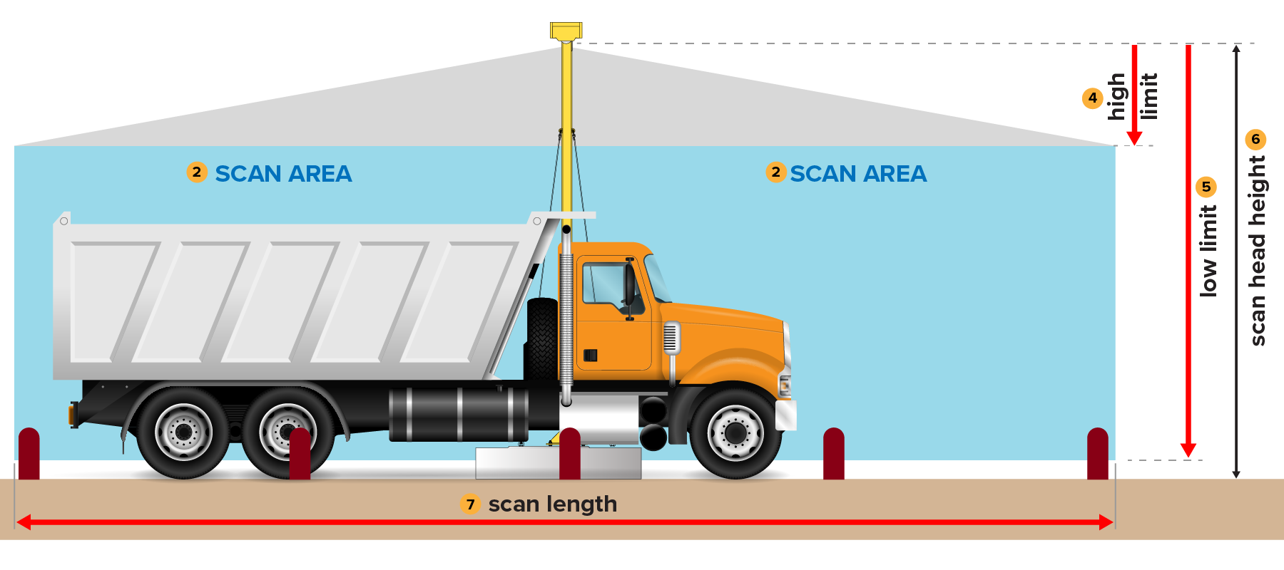
The scan area limits define rectangular areas in the:
- transverse plane (across the track, in line with the transverse laser beam)
- longitudinal plane (along the track, in line with the longitudinal laser beam).
When no vehicle is present, the scan area (#2) should be completely clear. This means no objects should protrude into the scan area from the sides or from below or above. Nothing should be visible to the lasers within the defined rectangular areas.
The only exception to this is that low side barriers or curbs less than about 1m (3.3’) high can be present at the extreme lower edges of the transverse scan area, as illustrated in the diagram on the previous page.
Examples of objects that need to be physically removed from the scan area, or require scan area limits to be adjusted if they cannot be removed, are:
- overhanging branches or cables
- high side barriers or walls
- rises in ground level far from the scan head
- leading or following vehicles and other traffic.
Scan width (#1)
Scan width is the overall width of the scan area.
This should generally be about 10-15% wider than the physically defined track width, but the scan area must fall completely inside any barriers or other objects higher than about 1m above ground that are visible to the transverse laser beam.
The scan width must be wide enough that vehicles are fully within the scan area during scanning. This includes allowance for off-centre truck position.
The track should be physically limited to the narrowest feasible width for the vehicles to be scanned.
The default scan width is 3.4m (11’) for standard on-road truck and trailer units. This value is intended for use with a track width physically limited to 3m (10’).
Scan length (#7)
Scan length is the overall length of the scan area.
The scan area on either side of the scan head must be at least as long as the longest single bin truck or individual trailer in a multi-bin vehicle combination to be scanned. The scan length must be double this.
The default scan length is 33m (108’). This is the maximum possible length.
As long as the requirements above are met, the scan length can be reduced to avoid objects protruding into the scan area far from the scan head. This includes temporary objects such as leading or following vehicles, or other traffic near the LVS.
Low limit (#5)
Low limit is the vertical distance from the laser zero point in the scan head to the bottom of the scan area.
Adjust this setting only when the bottom of the scan area needs to be raised because the ground profile or objects on the ground rise into the scan area at either end or either side of the track.
The bottom of the scan area must be lower than the lowest point on the internal floor of any empty truck/trailer bins that will be scanned.
The default low limit sets the bottom of the scan area at 125mm (4.9”) above ground level.
High limit (#4)
High limit is the vertical distance from the laser zero point in the scan head to the top of the scan area.
Adjust this setting only when the top of the scan area needs to be lowered to avoid overhead objects such as cables, mounting structures, tree branches, and so on that are lower than the scan head but within the defined width or length of the scan area.
The top of the scan area must be higher than the highest point on any vehicle or load that will be scanned.
The default high limit sets the top of the scan area at 400mm (15.7”) below the laser zero point.
Scan area viewer
The scan area viewer can be opened from the System screen on the LVS operator console. (See System Tools in the LVS 3 Series Operator Manual).
It shows the:
- full measured scan profile
- defined scan area for the selected laser direction.
It allows scan area limits to be adjusted.
Trade certified system users can view the scan area but maintenance/servicing level or higher access is required to adjust the scan area limits.
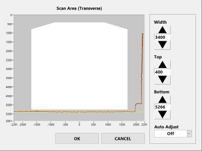
Scan area viewer components
| Component | Description |
|---|---|
| The measured scan profile for the selected laser direction | Shown in brown |
| The scan area | The white region defined by the limit settings:
|
| Region outside the scan area | The dark grey region |
Scan area settings and profiles
All limit values are in millimetres regardless of LVS regional settings. The horizontal/vertical aspect ratio is not to scale.
When no truck is present, the entire measured scan profile must be outside the scan area, as shown in the example above. This includes:
- the ground
- side barriers
- walls
- overhead branches
- cables
- other protrusions above ground level.
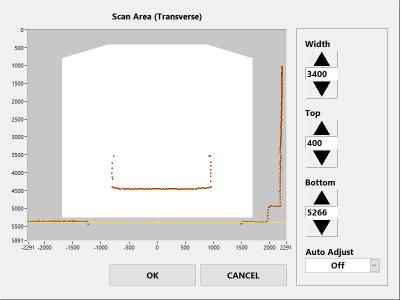
Trucks must be completely inside the scan area during scanning. This can be confirmed by driving trucks through the scan area with the scan area viewer window open, as in the example shown below.
All points on an empty or loaded truck scan profile must be within the white area. The scan area must allow for the largest trucks that will be scanned, fully loaded and shifted sideways (off-centre) to either side of the defined scan track.
Adjust scan area limits only if the default values are not suitable.
Scan head alignment must be complete and the scan track defined, with any barriers in place before adjusting scan area limits (see Appendix 2 – Scan head installation and alignment in the LVS 3 Series Operator Manual).
Auto adjust
Auto adjust automatically adjusts the boundary of the scan area and records a non-rectangular scan area for either laser direction.
It is intended for underground installs where irregular tunnel walls, overhead cables and so on make it difficult to define a clear rectangular region with enough width and height to include all truck scan profile points.
It can also be used for any situation where protrusions into the scan area exist but do not block the laser view of the truck.
The Auto Adjust option is on the scan area viewer and has three states.
| State | Description |
|---|---|
| Off | The scan area is defined by the scan area limits only. |
| Update | The border of the scan area automatically adjusts around any scan profile protrusions into the rectangular region defined by the scan area limits. This creates a non-rectangular scan area limit profile with a slight margin around any protrusions.
The scan area limit profile is continuously updated while auto adjust mode is set to ‘Update’. |
| Locked | The scan area limit profile is locked to its current value and stops updating. This is saved permanently when the scan area viewer is closed with the OK button. |
Auto Adjust example
Consider an underground mine installation in a tunnel with irregular walls.
The transverse scan area limits are set so the scan area is wide enough to allow for off-centre position of trucks during scanning and high enough for the highest load. However, the tunnel walls protrude into the scan area:
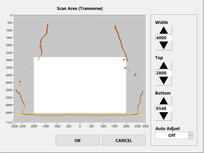
The top of the scan area can be lowered to clear the walls, but this may be too low for fully loaded trucks:
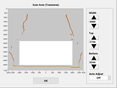
The width can be reduced to clear the walls but this will not provide tolerance for off-centre position of the truck:
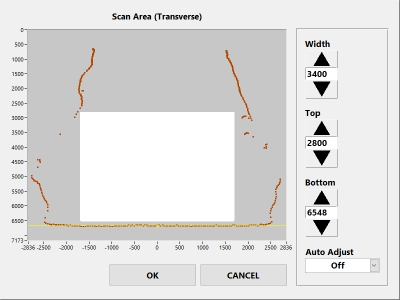
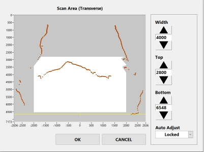
In this case, Auto Adjust is enabled:
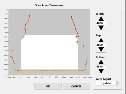
The resulting scan area has the same overall target height and width as the original rectangular region but avoids the tunnel walls
The scan area is wide enough to allow sideways shift to either side of the scan track and high enough in the central region to include the peak of the load on a highly loaded truck:
In this Article
Introduction
The Load Volume Scanner (LVS) scan area is where the LVS looks for trucks.
Trucks must be completely within the scan area during scanning and anything outside this area will be ignored.
The scan area is defined by settings normally set by Loadscan technical staff at the time of initial installation.
In some cases, the scan area limits may need to be adjusted for different installation sites or different truck types.
This document explains the scan area settings and how to adjust them.
The scan area
Scan area limits should be adjusted only if advised by Loadscan technical support. They cannot be adjusted by end-users on trade certified LVS systems.
The scan area is defined by limit settings as shown below.


The scan area limits define rectangular areas in the:
- transverse plane (across the track, in line with the transverse laser beam)
- longitudinal plane (along the track, in line with the longitudinal laser beam).
When no vehicle is present, the scan area (#2) should be completely clear. This means no objects should protrude into the scan area from the sides or from below or above. Nothing should be visible to the lasers within the defined rectangular areas.
The only exception to this is that low side barriers or curbs less than about 1m (3.3’) high can be present at the extreme lower edges of the transverse scan area, as illustrated in the diagram on the previous page.
Examples of objects that need to be physically removed from the scan area, or require scan area limits to be adjusted if they cannot be removed, are:
- overhanging branches or cables
- high side barriers or walls
- rises in ground level far from the scan head
- leading or following vehicles and other traffic.
Scan width (#1)
Scan width is the overall width of the scan area.
This should generally be about 10-15% wider than the physically defined track width, but the scan area must fall completely inside any barriers or other objects higher than about 1m above ground that are visible to the transverse laser beam.
The scan width must be wide enough that vehicles are fully within the scan area during scanning. This includes allowance for off-centre truck position.
The track should be physically limited to the narrowest feasible width for the vehicles to be scanned.
The default scan width is 3.4m (11’) for standard on-road truck and trailer units. This value is intended for use with a track width physically limited to 3m (10’).
Scan length (#7)
Scan length is the overall length of the scan area.
The scan area on either side of the scan head must be at least as long as the longest single bin truck or individual trailer in a multi-bin vehicle combination to be scanned. The scan length must be double this.
The default scan length is 33m (108’). This is the maximum possible length.
As long as the requirements above are met, the scan length can be reduced to avoid objects protruding into the scan area far from the scan head. This includes temporary objects such as leading or following vehicles, or other traffic near the LVS.
Low limit (#5)
Low limit is the vertical distance from the laser zero point in the scan head to the bottom of the scan area.
Adjust this setting only when the bottom of the scan area needs to be raised because the ground profile or objects on the ground rise into the scan area at either end or either side of the track.
The bottom of the scan area must be lower than the lowest point on the internal floor of any empty truck/trailer bins that will be scanned.
The default low limit sets the bottom of the scan area at 125mm (4.9”) above ground level.
High limit (#4)
High limit is the vertical distance from the laser zero point in the scan head to the top of the scan area.
Adjust this setting only when the top of the scan area needs to be lowered to avoid overhead objects such as cables, mounting structures, tree branches, and so on that are lower than the scan head but within the defined width or length of the scan area.
The top of the scan area must be higher than the highest point on any vehicle or load that will be scanned.
The default high limit sets the top of the scan area at 400mm (15.7”) below the laser zero point.
Scan area viewer
The scan area viewer can be opened from the System screen on the LVS operator console. (See System Tools in the LVS 3 Series Operator Manual).
It shows the:
- full measured scan profile
- defined scan area for the selected laser direction.
It allows scan area limits to be adjusted.
Trade certified system users can view the scan area but maintenance/servicing level or higher access is required to adjust the scan area limits.

Scan area viewer components
| Component | Description |
|---|---|
| The measured scan profile for the selected laser direction | Shown in brown |
| The scan area | The white region defined by the limit settings:
|
| Region outside the scan area | The dark grey region |
Scan area settings and profiles
All limit values are in millimetres regardless of LVS regional settings. The horizontal/vertical aspect ratio is not to scale.
When no truck is present, the entire measured scan profile must be outside the scan area, as shown in the example above. This includes:
- the ground
- side barriers
- walls
- overhead branches
- cables
- other protrusions above ground level.
Trucks must be completely inside the scan area during scanning. This can be confirmed by driving trucks through the scan area with the scan area viewer window open, as in the example shown below.
All points on an empty or loaded truck scan profile must be within the white area. The scan area must allow for the largest trucks that will be scanned, fully loaded and shifted sideways (off-centre) to either side of the defined scan track.

Adjust scan area limits only if the default values are not suitable.
Scan head alignment must be complete and the scan track defined, with any barriers in place before adjusting scan area limits (see Appendix 2 – Scan head installation and alignment in the LVS 3 Series Operator Manual).
Auto adjust
Auto adjust automatically adjusts the boundary of the scan area and records a non-rectangular scan area for either laser direction.
It is intended for underground installs where irregular tunnel walls, overhead cables and so on make it difficult to define a clear rectangular region with enough width and height to include all truck scan profile points.
It can also be used for any situation where protrusions into the scan area exist but do not block the laser view of the truck.
The Auto Adjust option is on the scan area viewer and has three states.
| State | Description |
|---|---|
| Off | The scan area is defined by the scan area limits only. |
| Update | The border of the scan area automatically adjusts around any scan profile protrusions into the rectangular region defined by the scan area limits. This creates a non-rectangular scan area limit profile with a slight margin around any protrusions.
The scan area limit profile is continuously updated while auto adjust mode is set to ‘Update’. |
| Locked | The scan area limit profile is locked to its current value and stops updating. This is saved permanently when the scan area viewer is closed with the OK button. |
Auto Adjust example
Consider an underground mine installation in a tunnel with irregular walls.
The transverse scan area limits are set so the scan area is wide enough to allow for off-centre position of trucks during scanning and high enough for the highest load. However, the tunnel walls protrude into the scan area:

The top of the scan area can be lowered to clear the walls, but this may be too low for fully loaded trucks:

The width can be reduced to clear the walls but this will not provide tolerance for off-centre position of the truck:

In this case, Auto Adjust is enabled:

The resulting scan area has the same overall target height and width as the original rectangular region but avoids the tunnel walls
The scan area is wide enough to allow sideways shift to either side of the scan track and high enough in the central region to include the peak of the load on a highly loaded truck:

