Step 1. Mounting the kiosk
The kiosk is the central point of the system and contains the operator touch panel and power connections. It needs to be firmly mounted in a suitable location where it can be easily and safely accessed by the operator.

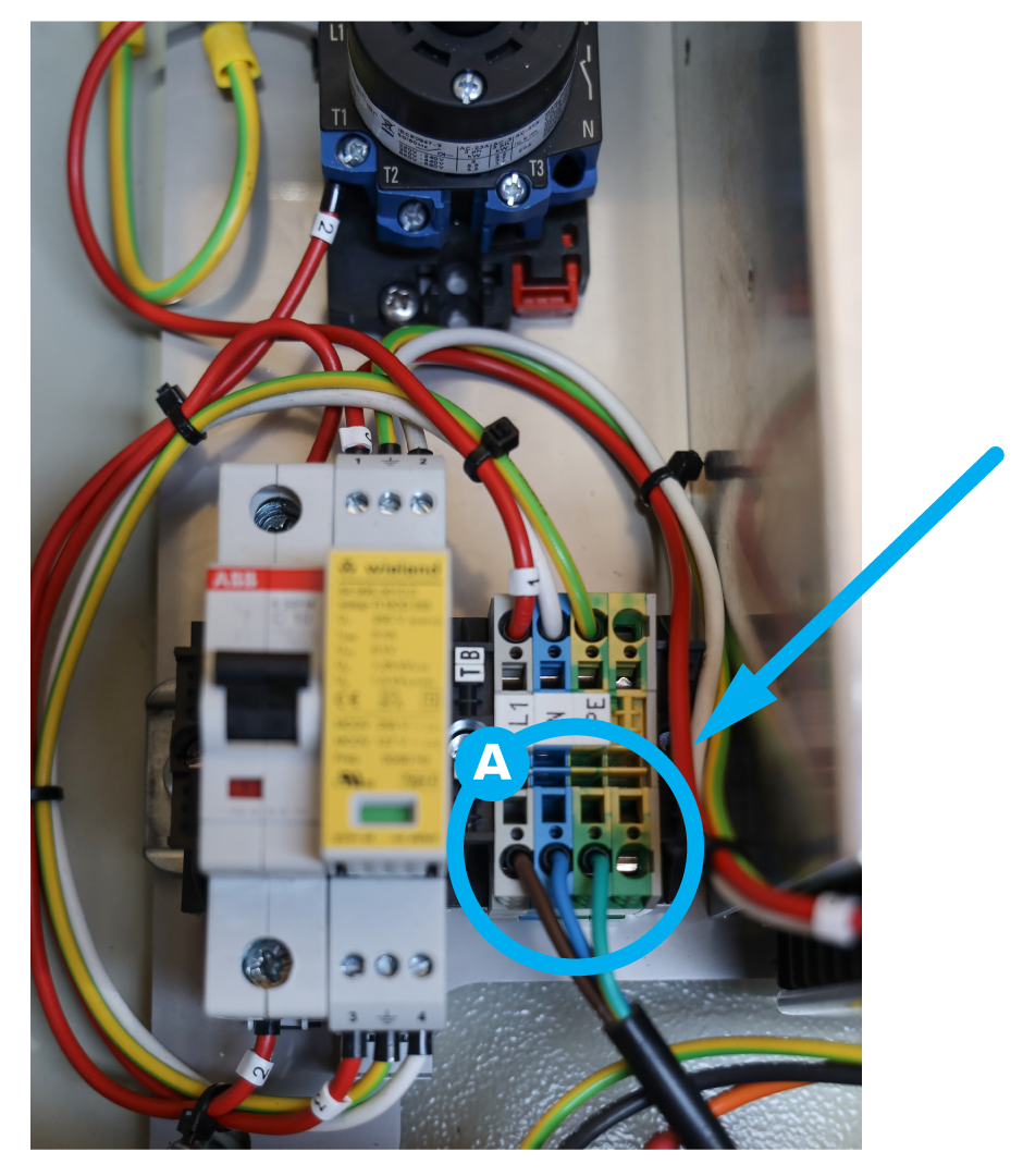
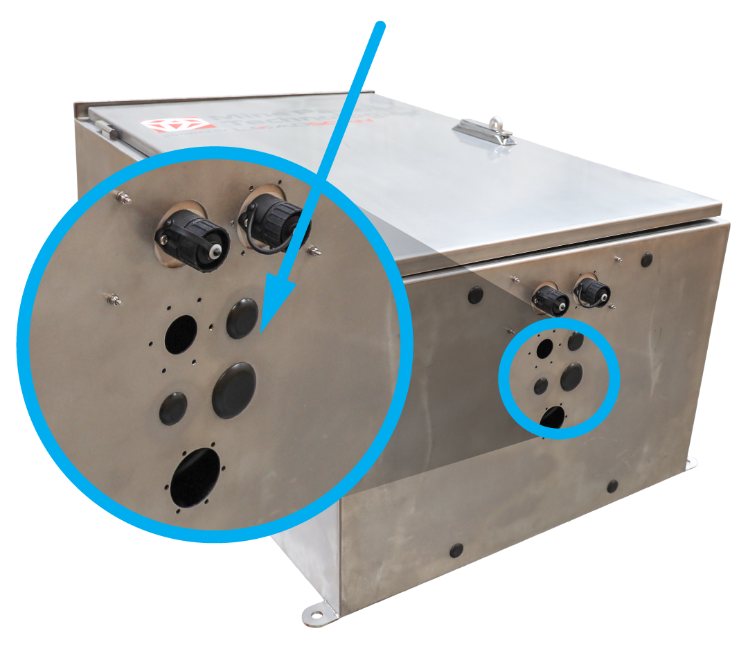
The kiosk needs to be connected to your local 110-240v 50/60Hz power supply (max. 4A) via the electrical connection points (Point A) inside the Power Box through one of the blank holes in the base of the Power Box and kiosk.
Step 2. Network cabling to kiosk
To access external systems, the MPS system needs to be connected to the local network through the network connection point on the rear of the computer touch panel unit.
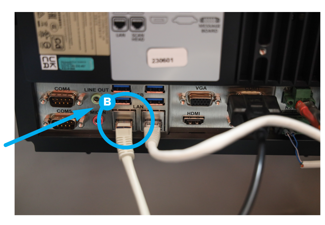
Remove the touch panel unit by loosening the screws and lifting it out to expose the rear of the computer. Route the ethernet cable into the kiosk, up behind the computer and plug the ethernet (LAN) cable into the dedicated RJ45 ethernet port on the rear of the computer (Point B ).
Step 3. Cabling kiosk to scan head.
The MPS system has an armoured cable that connects the kiosk to the scan head.
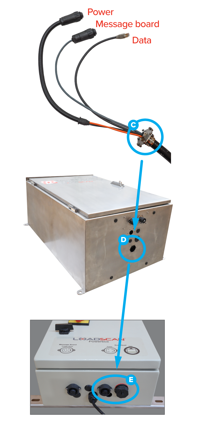
At the kiosk end of the cable, feed the cable ends (power, data, message board connection) up inside the kiosk, then fix the stainless steel gland (Point C) to the base of the kiosk enclosure, using six M3 screws and washers (Point D).
The power and data connections then plug into the base of the Power Box (Point E), labelled Scan Head.
Step 4. Message board cabling
The external message boards can be connected either to the base of the kiosk box, or to the scan head.
The cables for the external message board are 30m long. If they reach from their intended mounting location to the kiosk box, they can be plugged into the message board connection box located in the base of the kiosk (F), which will then need to be connected to the connection point on the Power Box marked ‘Message Board’ (Point G).
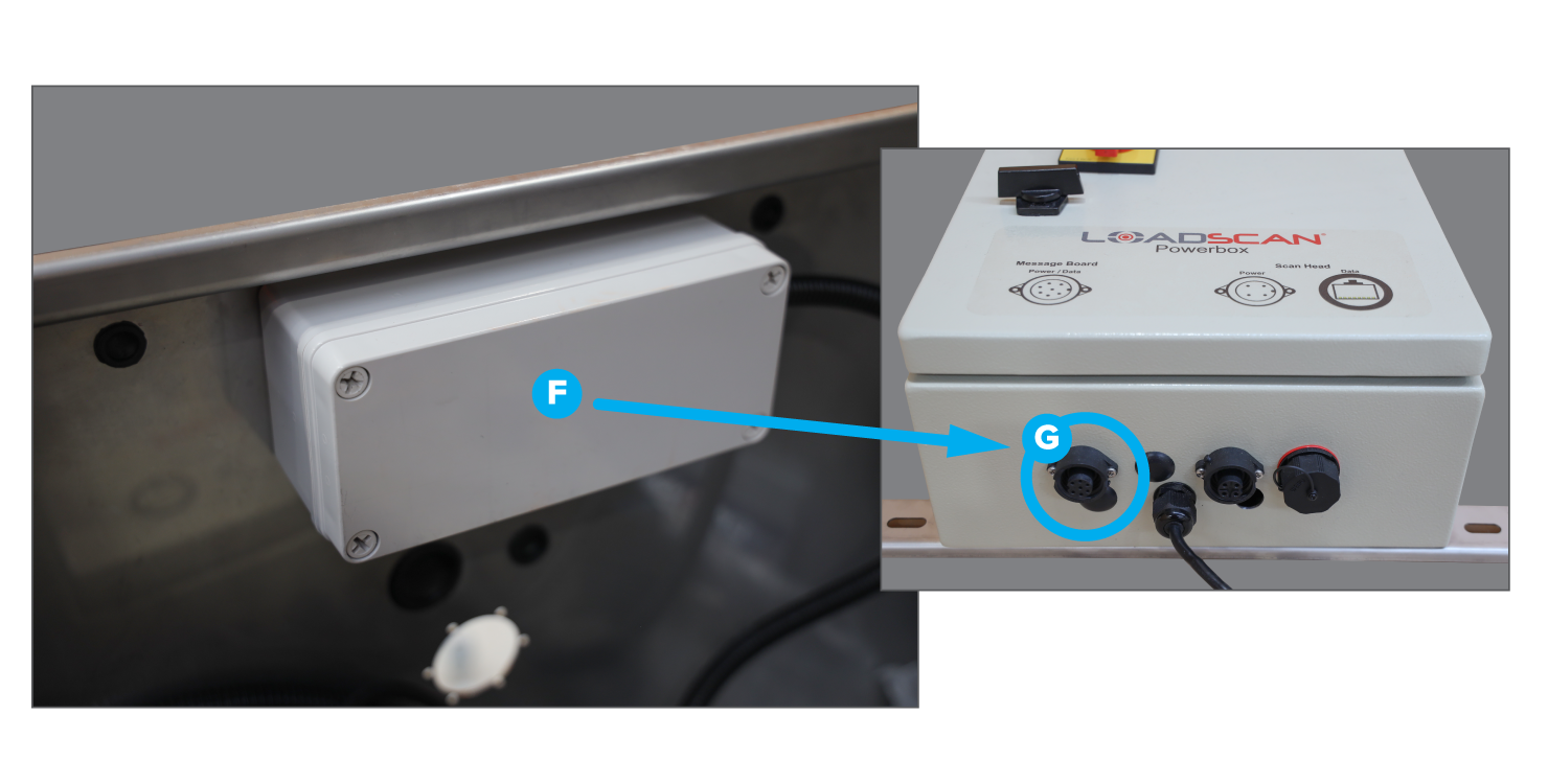
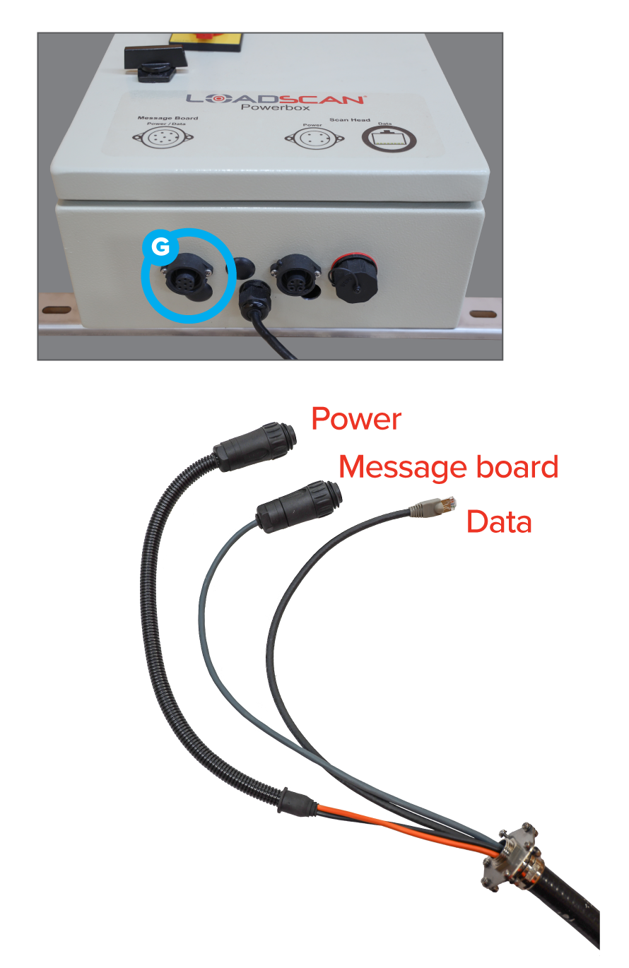
If the message board is to connect directly to the scan head, the kiosk end of the scan head cable plugs straight into the connection point on the Power Box marked ‘Message Board’ (G).
(Note: If this connection method is NOT used, the message board plug on the scan head cable will be surplus and remain unused.)
Keep the scan head cables coiled and safely stored while the scan head is being installed.
Step 5. Scan Head installation
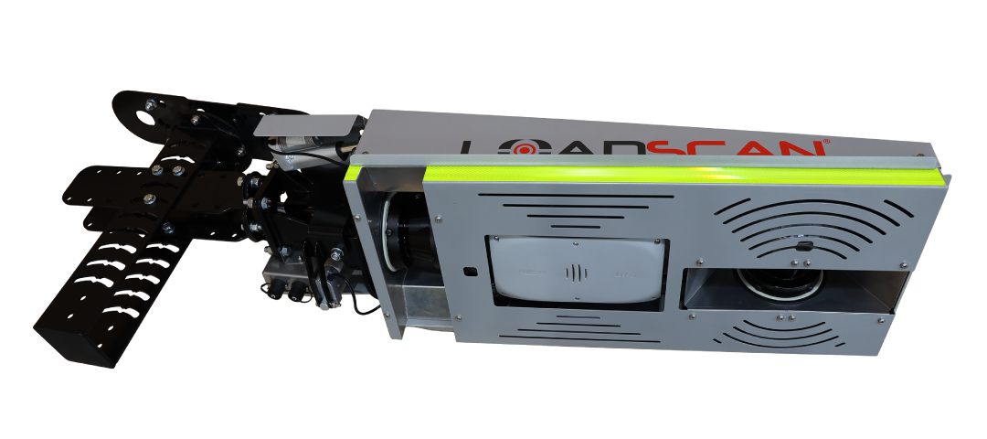
Mounting the scan head correctly is a crucial step in this install process.
The scan head MUST be in a tunnel that is [at least] 6.5m high.
The scan head MUST be installed above reasonably level ground of an even gradient.
The scan head MUST be mounted so the transverse laser is in the centre of the path typically driven by the trucks.
The mounting location can be determined by observing the path where trucks typically drive, finding the centreline of that path and then locating the corresponding point on the ceiling using a laser level. Once that point has been located, the ceiling bracket needs to be mounted to the tunnel ceiling with the central mounting holes exactly 1250mm to the left or right of the centreline (See Figure 1).
The scan head must be mounted perpendicular to the tunnel traffic flow; however it can go left-to-right or right-to-left.
This step is important as it allows a limited range of adjustment, if required.
Scan Head Installation (Pole/Side mount)
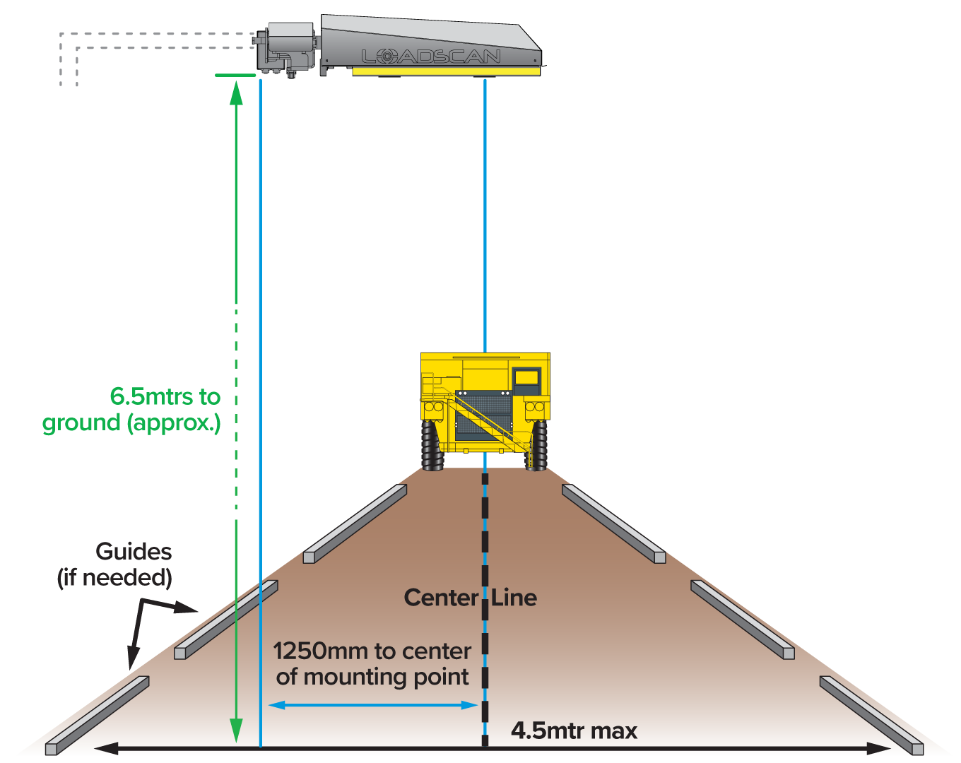
Figure 1. This diagram illustrates the positioning over a typical route taken by the trucks.
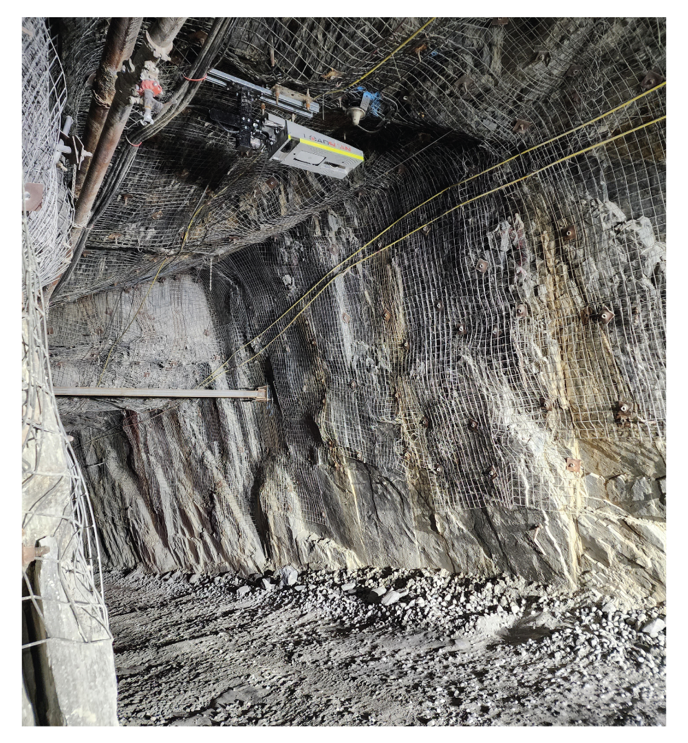
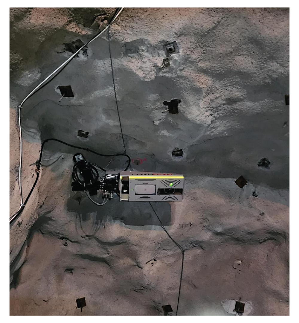
Examples of installations
Step 6. Scan head cable installation
Once the scan head has been installed, it needs to be connected to the kiosk via the scan head cable to provide power and communications between the scan head and the computer.
The connection cable feeds into the rear of the scan head (Point H) through into the termination box (Point J) on the side of the scan head bracket.
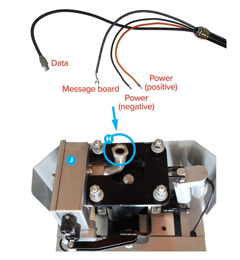
The connections inside the junction box are:
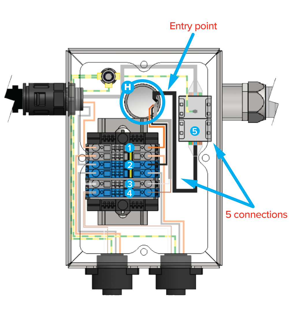
| Scanhead cable | Terminal Position |
|---|---|
| Orange (+24 VDC) (1) | Top grey terminal block |
| Black (-24 VDC) (2) | Top blue terminal block |
| Message board White (3) | Bottom grey terminal block |
| Message board Brown (4) | Bottom blue terminal block |
| RJ45 (scanhead data) (5) | RJ45 coupler |
Step 7. Message board connections
The message board cables can now be connected.
Orient the male end of the cables to the connection point at the kiosk or scan head (as per Step 4).
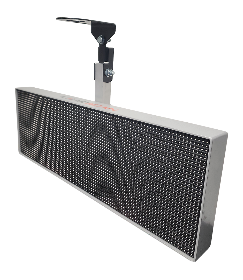
The message board is supplied with a ceiling mount bracket and need to be mounted as far down the tunnel as necessary so truck drivers can view them throughout the scanning process.
The message board cables can then be routed and plugged into either the scan head or the kiosk (as per Step 4).
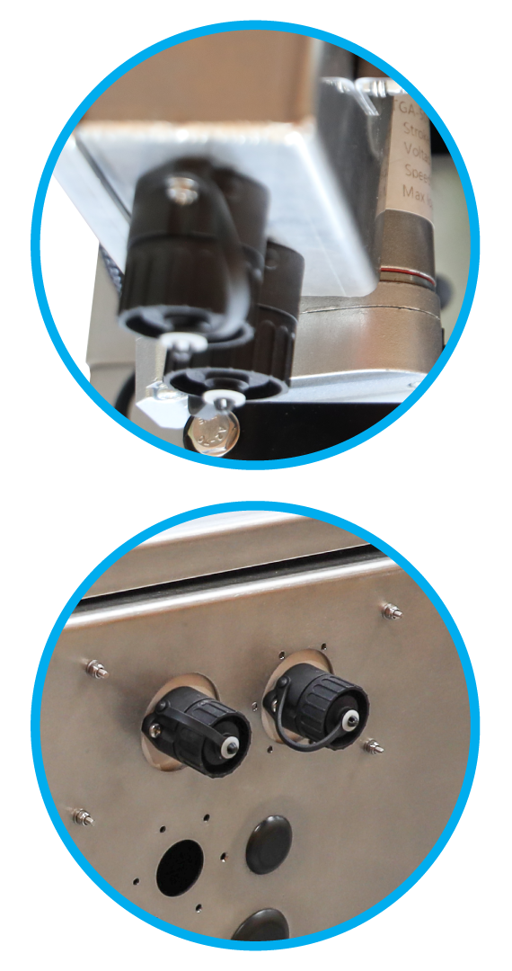
a) If they are going to connect to the scan head, use the sockets on the base of the junction box inside the scan head;
b) Alternatively, the cables can be routed back to the kiosk and plugged into the two sockets on the base of the kiosk.
Step 8. System check
The physical install of the system has now been completed, so it is possible to switch it on and check it is operational.
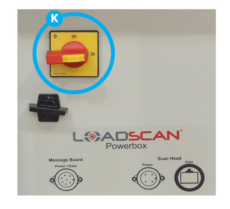
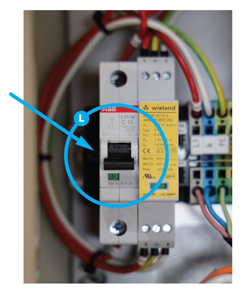
At this stage, you can switch the MPS system on by switching on the main circuit breaker inside the power box (L), then using the main isolator switch (K) to power up the unit.
When the system is switched on, check the following:
- The computer screen lights up and shows the Loadscan screen;
- The message board screens light up;
- The scan head shows indicator lights on the laser units
(Note: These are small LEDs and may be difficult to see).

In this Article
Step 1. Mounting the kiosk
The kiosk is the central point of the system and contains the operator touch panel and power connections. It needs to be firmly mounted in a suitable location where it can be easily and safely accessed by the operator.


The kiosk needs to be connected to your local 110-240v 50/60Hz power supply (max. 4A) via the electrical connection points (Point A) inside the Power Box through one of the blank holes in the base of the Power Box and kiosk.

Step 2. Network cabling to kiosk
To access external systems, the MPS system needs to be connected to the local network through the network connection point on the rear of the computer touch panel unit.
Remove the touch panel unit by loosening the screws and lifting it out to expose the rear of the computer. Route the ethernet cable into the kiosk, up behind the computer and plug the ethernet (LAN) cable into the dedicated RJ45 ethernet port on the rear of the computer (Point B ).

Step 3. Cabling kiosk to scan head.
The MPS system has an armoured cable that connects the kiosk to the scan head.
At the kiosk end of the cable, feed the cable ends (power, data, message board connection) up inside the kiosk, then fix the stainless steel gland (Point C) to the base of the kiosk enclosure, using six M3 screws and washers (Point D).
The power and data connections then plug into the base of the Power Box (Point E), labelled Scan Head.
Step 4. Message board cabling
The external message boards can be connected either to the base of the kiosk box, or to the scan head.
The cables for the external message board are 30m long. If they reach from their intended mounting location to the kiosk box, they can be plugged into the message board connection box located in the base of the kiosk (F), which will then need to be connected to the connection point on the Power Box marked ‘Message Board’ (Point G).


If the message board is to connect directly to the scan head, the kiosk end of the scan head cable plugs straight into the connection point on the Power Box marked ‘Message Board’ (G).
(Note: If this connection method is NOT used, the message board plug on the scan head cable will be surplus and remain unused.)
Keep the scan head cables coiled and safely stored while the scan head is being installed.
Step 5. Scan Head installation

Mounting the scan head correctly is a crucial step in this install process.
The scan head MUST be in a tunnel that is [at least] 6.5m high.
The scan head MUST be installed above reasonably level ground of an even gradient.
The scan head MUST be mounted so the transverse laser is in the centre of the path typically driven by the trucks.
The mounting location can be determined by observing the path where trucks typically drive, finding the centreline of that path and then locating the corresponding point on the ceiling using a laser level. Once that point has been located, the ceiling bracket needs to be mounted to the tunnel ceiling with the central mounting holes exactly 1250mm to the left or right of the centreline (See Figure 1).
The scan head must be mounted perpendicular to the tunnel traffic flow; however it can go left-to-right or right-to-left.
This step is important as it allows a limited range of adjustment, if required.
Scan Head Installation (Pole/Side mount)

Figure 1. This diagram illustrates the positioning over a typical route taken by the trucks.


Examples of installations
Step 6. Scan head cable installation
Once the scan head has been installed, it needs to be connected to the kiosk via the scan head cable to provide power and communications between the scan head and the computer.
The connection cable feeds into the rear of the scan head (Point H) through into the termination box (Point J) on the side of the scan head bracket.

The connections inside the junction box are:

| Scanhead cable | Terminal Position |
|---|---|
| Orange (+24 VDC) (1) | Top grey terminal block |
| Black (-24 VDC) (2) | Top blue terminal block |
| Message board White (3) | Bottom grey terminal block |
| Message board Brown (4) | Bottom blue terminal block |
| RJ45 (scanhead data) (5) | RJ45 coupler |
Step 7. Message board connections
The message board cables can now be connected.
Orient the male end of the cables to the connection point at the kiosk or scan head (as per Step 4).
The message board is supplied with a ceiling mount bracket and need to be mounted as far down the tunnel as necessary so truck drivers can view them throughout the scanning process.
The message board cables can then be routed and plugged into either the scan head or the kiosk (as per Step 4).

a) If they are going to connect to the scan head, use the sockets on the base of the junction box inside the scan head;
b) Alternatively, the cables can be routed back to the kiosk and plugged into the two sockets on the base of the kiosk.

Step 8. System check
The physical install of the system has now been completed, so it is possible to switch it on and check it is operational.
At this stage, you can switch the MPS system on by switching on the main circuit breaker inside the power box (L), then using the main isolator switch (K) to power up the unit.


When the system is switched on, check the following:
- The computer screen lights up and shows the Loadscan screen;
- The message board screens light up;
- The scan head shows indicator lights on the laser units
(Note: These are small LEDs and may be difficult to see).

