Introduction
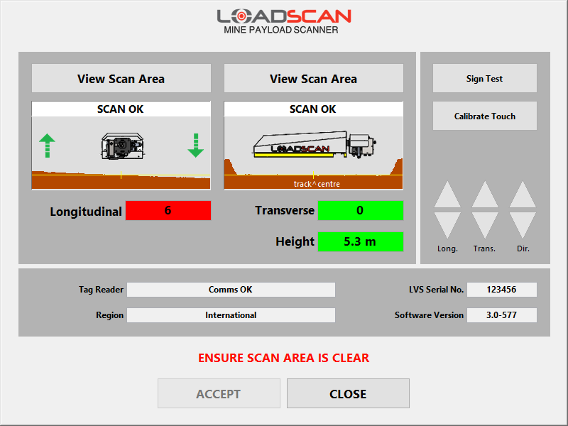
The System screen (figure 37) provides tools for:
- installing and aligning the scan head
- viewing and adjusting the scan area limits
- performing system hardware checks.
Access is from the SYSTEM button on the Main screen. The ‘system’ password is required.

Figure 37 – operator console System screen
Scan head installation and alignment is required when:
- the scan head is installed on a new site
- the scan head is moved significantly
- the ground profile changes.
If ‘SYSTEM SETUP REQUIRED’ displays on the LVS Main screen after system start-up, open the System screen and check the alignment displays.
This message indicates that one or both ground profiles are significantly different from those previously recorded. Scan head alignment or track maintenance may be required before the system can proceed to ready to ‘Ready’ state.
Scan head alignment controls and indicators
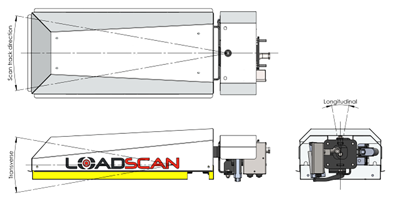
The MPS mounting system determines the installed position of the scan head. An automated 3-axis mounting bracket is incorporated into MPS-3BMP and MPS-3CMX scan heads, as shown in figure 38. This is used for fine-tuning the scan head alignment.
The MPS-3TMM has adjustable drop-down trailer legs for scan head alignment.

Figure 38 – MPS-3BMP and MPS-3CMX scan head adjustment axes
The System screen includes control buttons for moving the mounting bracket and indicator displays that provide the current scan head alignment status.
| Contols and indicators | Description |
|---|---|
| Bracket control buttons (MPS-3BMP and MPS-3CMX only) |
The Long. buttons roll the scan head to adjust the longitudinal laser beam alignment.
The trans. buttons tilt the scan head to adjust the transverse laser beam alignment. The Dir. Buttons swing the scan head laterally to adjust the direction of the laser beams along the ground. |
| Longitudinal and transverse ground profiles | These show the measured ground profiles in each laser scanning direction. They provide a graphical indication of the evenness of the scan track and the relative alignment of the scan head. |
| Diagrammatic views of the scan head | These provide orientation references for the ground profiles. |
| Longitudinal and Transverse alignment indicators | The Longitudinal and Transverse indicators show computed measures of relative alignment between the scan head and the ground in the respective directions.
These values should be as close as possible to zero. If the value is acceptable the background colour is green. If the value is outside the allowable range, the background colour is red. Move the scan head with the corresponding bracket control buttons to make adjustments. |
| Height indicator | The Height is the distance from the scan head to the ground.
If the value is acceptable the background colour is green. If the value is outside the allowable range, the background colour is red. |
The scan head alignment procedure is fully documented in Appendix 2 – Scan head installation and alignment.
Message board alignment display
The alignment and height values are also displayed on the message board when the System screen is open. This makes it possible to perform scan head adjustments without also viewing the operator console screen.
Labels displayed on message board:
- ‘T’ – transverse alignment
- ‘L’ – longitudinal alignment
- ‘H’ – height.
Scan area viewer
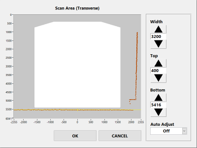
The View Scan Area buttons above each ground profile window open the Scan Area Viewer (figure 39).
For the selected laser direction, the viewer:
- displays the full measured scan profile
- displays the defined scan area
- allows scan area limits to be adjusted (except for trade certified systems which require maintenance/servicing level, or higher, access).

Figure 39 – operator console Scan Area Viewer
The white area is the scan area defined by limit settings. The grey area is outside the scan area.
Trucks must be completely inside the scan area during a scan.
The entire measured scan profile (brown) must be outside the scan area when no truck is present. This includes the ground and any side barriers, trees, cables or other protrusions above ground level.
Scan area limits should be adjusted only if advised by Loadscan technical support and with reference to the supplementary LVS support document Loadscan LVS – Adjusting Scan Area Limits.
System hardware checks
The System screen can be used to check that system hardware is operational.
- Laser scanner status messages are displayed above longitudinal and transverse profiles. (See Appendix 3 – Status messages and error codes.)
- The Tag Reader field indicates the status of the RFID tag reader. To test if the tag reader is successfully reading tags, hold a tag, flat face up, under the centre of the scan head or drive a truck with tag fitted below the scan head. If the tag is detected, the tag code will display for a few seconds on the message board and in the Tag Reader box.
- The Sign Test button writes a test message to the message board.
- Use the Calibrate Touch button to re-calibrate the touch-screen pointer position if this does not move exactly to finger push locations.
- The MPS Serial Number, Software Version and Region settings are also displayed on this screen. Please report these when requesting technical support from Loadscan.
In this Article
Introduction
The System screen (figure 37) provides tools for:
- installing and aligning the scan head
- viewing and adjusting the scan area limits
- performing system hardware checks.
Access is from the SYSTEM button on the Main screen. The ‘system’ password is required.

Figure 37 – operator console System screen
Scan head installation and alignment is required when:
- the scan head is installed on a new site
- the scan head is moved significantly
- the ground profile changes.
If ‘SYSTEM SETUP REQUIRED’ displays on the LVS Main screen after system start-up, open the System screen and check the alignment displays.
This message indicates that one or both ground profiles are significantly different from those previously recorded. Scan head alignment or track maintenance may be required before the system can proceed to ready to ‘Ready’ state.
Scan head alignment controls and indicators
The MPS mounting system determines the installed position of the scan head. An automated 3-axis mounting bracket is incorporated into MPS-3BMP and MPS-3CMX scan heads, as shown in figure 38. This is used for fine-tuning the scan head alignment.
The MPS-3TMM has adjustable drop-down trailer legs for scan head alignment.

Figure 38 – MPS-3BMP and MPS-3CMX scan head adjustment axes
The System screen includes control buttons for moving the mounting bracket and indicator displays that provide the current scan head alignment status.
| Contols and indicators | Description |
|---|---|
| Bracket control buttons (MPS-3BMP and MPS-3CMX only) |
The Long. buttons roll the scan head to adjust the longitudinal laser beam alignment.
The trans. buttons tilt the scan head to adjust the transverse laser beam alignment. The Dir. Buttons swing the scan head laterally to adjust the direction of the laser beams along the ground. |
| Longitudinal and transverse ground profiles | These show the measured ground profiles in each laser scanning direction. They provide a graphical indication of the evenness of the scan track and the relative alignment of the scan head. |
| Diagrammatic views of the scan head | These provide orientation references for the ground profiles. |
| Longitudinal and Transverse alignment indicators | The Longitudinal and Transverse indicators show computed measures of relative alignment between the scan head and the ground in the respective directions.
These values should be as close as possible to zero. If the value is acceptable the background colour is green. If the value is outside the allowable range, the background colour is red. Move the scan head with the corresponding bracket control buttons to make adjustments. |
| Height indicator | The Height is the distance from the scan head to the ground.
If the value is acceptable the background colour is green. If the value is outside the allowable range, the background colour is red. |
The scan head alignment procedure is fully documented in Appendix 2 – Scan head installation and alignment.
Message board alignment display
The alignment and height values are also displayed on the message board when the System screen is open. This makes it possible to perform scan head adjustments without also viewing the operator console screen.
Labels displayed on message board:
- ‘T’ – transverse alignment
- ‘L’ – longitudinal alignment
- ‘H’ – height.
Scan area viewer
The View Scan Area buttons above each ground profile window open the Scan Area Viewer (figure 39).
For the selected laser direction, the viewer:
- displays the full measured scan profile
- displays the defined scan area
- allows scan area limits to be adjusted (except for trade certified systems which require maintenance/servicing level, or higher, access).

Figure 39 – operator console Scan Area Viewer
The white area is the scan area defined by limit settings. The grey area is outside the scan area.
Trucks must be completely inside the scan area during a scan.
The entire measured scan profile (brown) must be outside the scan area when no truck is present. This includes the ground and any side barriers, trees, cables or other protrusions above ground level.
Scan area limits should be adjusted only if advised by Loadscan technical support and with reference to the supplementary LVS support document Loadscan LVS – Adjusting Scan Area Limits.
System hardware checks
The System screen can be used to check that system hardware is operational.
- Laser scanner status messages are displayed above longitudinal and transverse profiles. (See Appendix 3 – Status messages and error codes.)
- The Tag Reader field indicates the status of the RFID tag reader. To test if the tag reader is successfully reading tags, hold a tag, flat face up, under the centre of the scan head or drive a truck with tag fitted below the scan head. If the tag is detected, the tag code will display for a few seconds on the message board and in the Tag Reader box.
- The Sign Test button writes a test message to the message board.
- Use the Calibrate Touch button to re-calibrate the touch-screen pointer position if this does not move exactly to finger push locations.
- The MPS Serial Number, Software Version and Region settings are also displayed on this screen. Please report these when requesting technical support from Loadscan.
