The Settings screen (figure 19) provides options for customising the MPS configuration.
Access this screen from the SETTINGS button on the Main screen. The ‘system’ password is required.
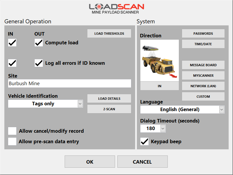
Figure 19 – operator console Settings screen
General operation settings
The General Operation section of the Settings screen provides options for:
- vehicles entering or leaving the site (See Defining ‘in’ and ‘out’ scan directions.)
- general options that apply for both scan directions.
If all direction specific options are disabled for one scan direction, scanning is disabled in that direction. This may be desirable where the LVS is used in only one direction but vehicles need to pass through the scan area in both directions.
Empty reference scans can always be performed in either direction.
| Setting | Description |
|---|---|
| Load Thresholds | Opens the Load Thresholds dialog to set load status reporting thresholds.
This button is only visible if load status reporting is enabled. |
| Compute load | Enable/disable load measurement for the corresponding scan direction. |
| Log all errors if ID known | Enable/disable error logging for the corresponding scan direction. When enabled, scans where the target vehicle(s) is identified by ID tag but no measurement result is reported because of errors, will be logged to file. A record of the vehicle trip for a failed scan is created, without measurement data. This function is typically used to record the time, date and vehicle ID(s) for failed scans where all vehicles have ID tags fitted and do not stop after scanning (no load details prompts).If this option is disabled then error scans that do not result in a load measurement will not be recorded. If Log all errors if ID known is enabled and Compute load is disabled, vehicles with ID tags will be recorded, but marked as TRACKING ONLY (i.e. without measurement data). |
| Site name | The site name appears at the top of the Main screen, on printed tickets and in measurement records. |
| Allow cancel / modify record | If enabled, a scan record can be cancelled or load details modified up to two minutes after a new load report.
See Cancel/Modify record. |
| Allow pre-scan data entry | If enabled, vehicle IDs and any configured load details can be pre-entered before performing a scan instead of after the scan. See Pre-scan data entry. |
| Vehicle identification | This selector allows the method of vehicle identification to be set:
|
Configuring load detail prompts
User-defined load details can be configured to record the load material, source, destination, or such like, together with measurement records.
To add or edit load detail prompts, use the Load Details button in the General Operation section of the Settings screen.
This displays the Load Details dialog (figure 20).
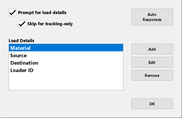
Figure 20 – operator console Load Details dialog
| Setting | Description |
|---|---|
| Prompt for Load Details | If enabled, the system prompts for keypad entry/selection of user-defined load details after every scan, before reporting and recording measurement data.
A basic load report is displayed on the message board while load detail prompts appear on the operator console screen after a scan. A load report will not appear on the operator console screen until all load details have been entered. A maximum of six user-defined load details can be created. |
| Skip for Tracking-Only | If enabled, load detail prompts will be skipped for tracking-only vehicle scans. (See Tracking only (no measurement).) |
| Load Details | The current list of user-defined load details in the order they will be prompted and recorded. Use this selector to select a specific load detail to edit or remove. |
| Add | Add a new user-defined load detail after any existing ones. (See Load detail properties below.) |
| Edit | Edit the selected load detail. (See Load detail properties below.) |
| Remove | Remove the selected load detail. |
| AUTO RESPONSES | Open the Auto-Responses dialog where automatic responses to load detail prompts can be set for selected vehicles. (See Automatic responses to load detail prompts.) |
Load detail properties
The Load Detail Properties dialog (figure 21) opens when a load detail is added or edited.
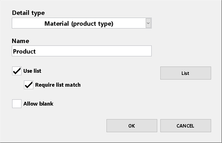
Fig 21 – operator console Load Detail Properties dialog
| Setting | Description |
|---|---|
| Detail type |
|
| Name | The name to assign to the load detail. The name should match the detail to be requested, such as ‘Load Source’, ‘Load Destination’ or ‘Driver’. |
| Use list | Enable/disable list selection on the load detail prompt. (See Load detail selection lists below.) |
| Require list match | If enabled, the text entered must exactly match one of the list items. If not enabled, any text can be entered. If Require list match is enabled and the selection list has only one item, that item is selected automatically without prompting. |
| Allow blank | If enabled, it is possible to close the prompt without entering any text. |
Load detail selection lists
For each configured load detail, it is possible to display a predefined selection list with the keypad prompt for quick and accurate text entry.
To create or update a selection list for a configured load detail:
- Select the load detail on the Load Details dialog (figure 20).
- Push the Edit button to open the Load Detail Properties dialog (figure 21).
- Push the List button to open the List dialog (figure 22).
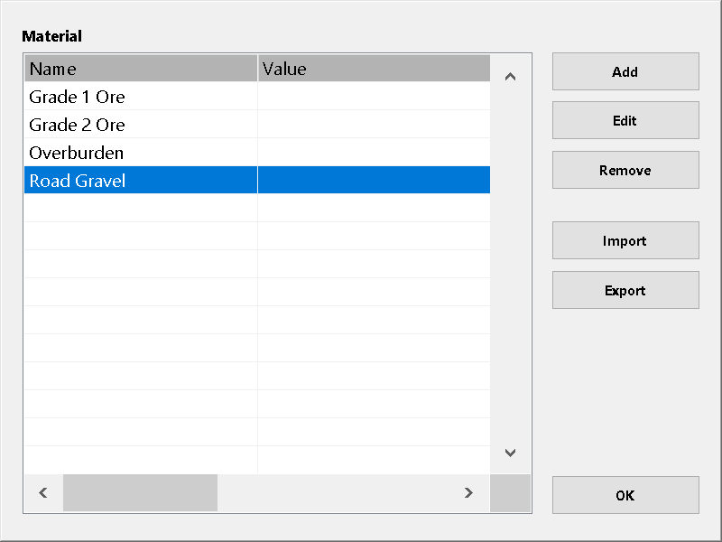
Fig 22 – operator console List dialog
Use the horizontal scrollbar to view hidden fields.
| Setting/button | Description |
|---|---|
| Add | Add a list item. (See List item fields below.)
If an existing list item is selected, the new item is inserted immediately before the selection. If no item is selected, the new item is appended to the end of the list. List item order is only important if using selection dependent list filters. (See the supplementary support document Loadscan LVS – Advanced Load Detail Options.) Lists are alphanumerically sorted for load detail selection. |
| Edit | Edit the selected list item. (See List item fields below.) |
| Remove | Remove the selected list item. |
| Import | Import a predefined list file from USB flash drive. The list can be created in advance on an office computer. (See How to generate and import a load detail selection list file below.) |
| Export | Export the list to file on USB flash drive for external editing, transfer to another MPS or backup. |
List item fields
The List Item dialog (figure 23) opens when a list item is added or edited.
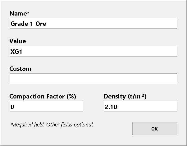
Figure 23 – operator console List Item dialog
Each list item has at least the following three fields:
| Field | Description |
|---|---|
| Name | The item name as it appears in the selection list. This field is required. |
| Value | The value that is output when name is selected. This is the text value that is shown on load reports and saved in measurement records. If not set, value will be the same as name. It may be desirable to output a different value than the name displayed on the selection list. For example, abbreviations or nicknames for selection and full names on load reports and measurement records. |
| Custom | An optional user-defined property associated with the list item and saved with measurement records. This can be for example, a ‘material code’ associated with a material name and required by external systems that process MPS measurement records. |
Additional fields may be present, depending on the load detail type. These are only required for specific custom functions and usage is detailed in the associated documentation.
For example, the ‘Density’ field present for the ‘Material (product type)’ load detail type is used for the weight estimate function. (See Weight estimate function.)
Refer to the supplementary support document Loadscan LVS – Advanced Load Detail Options for example usage of value and custom fields and additional advanced list functionality
How to generate and import a load detail selection list file
- Lists can be created in Microsoft® Notepad or a similar text editor:
1. Create the list as a text file with each item name on a new line.
If additional fields are required, add these after names with commas between fields, in the order they appear on the List Item dialog (figure 23).
Fields that are not required can be left blank (skip with comma only) and no fields after the last required field need to be entered.
Do not include commas in the text values.
1. Copy the list file to a USB flash drive with a file name that matches the load detail name. For example, if the load detail is “Product” the file name must be “Product.txt”.
2. Insert the USB drive into the operator console USB port and push the Import button on the List dialog.
If the import is successful, the list items will appear in the list display.
Defining ‘in’ and ‘out’ scan directions
Toggle the button below the Direction image in the System section of the Settings screen to match the direction of the truck shown, relative to the pictured scan head and corresponding to the actual direction for the installed MPS.
Time and date settings
The Time/Date button in the System section of the Settings screen opens the Time and Date dialog (figure 24) for setting the current time, date and time zone.
If the operator console is connected to a local network with internet access or a local NTP time server, the system time can be adjusted automatically.
When Adjust time automatically is enabled, the system will synchronize time with the time server specified in NTP Server.
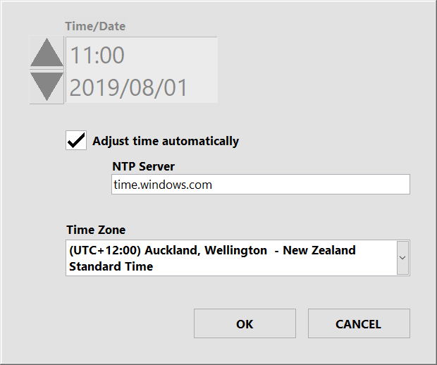
Figure 24 – operator console Time and Date dialog
If the operator console is connected to a local network with internet access or a local NTP time server, the system time can be adjusted automatically.
When Adjust time automatically is enabled, the system will synchronize time with the time server specified in NTP Server.
The NTP server can be specified by DNS name or IP address.
Time/Date can be adjusted manually only when automatic time adjustment is disabled.
Set Time Zone to match the region where your MPS is installed.
Note that time is displayed in 24-hour format and abbreviated, language-specific month names are used for on-screen date displays and on printed tickets.
Date and time are written to measurement record log files in the following ISO 8601 compliant format:
YYYY-MM-DD HH:MM:SS±hh:mm
Where ±hh:mm is the timezone offset from Universal Time (UTC).
This format provides compatibility for importing measurement records into databases and other software systems and is a widely accepted international format.
The current time is displayed at the top left of the operator console Main screen.
Language setting
If alternative languages or regional variants are installed for the MPS software, then the Language selector in the System section of the Settings screen can be used to switch between installed languages/regions.
The system must be re-started for language or region changes to take effect.
Password settings
The PASSWORDS button in the System section of the Settings screen opens the Password Settings dialog (figure 25).
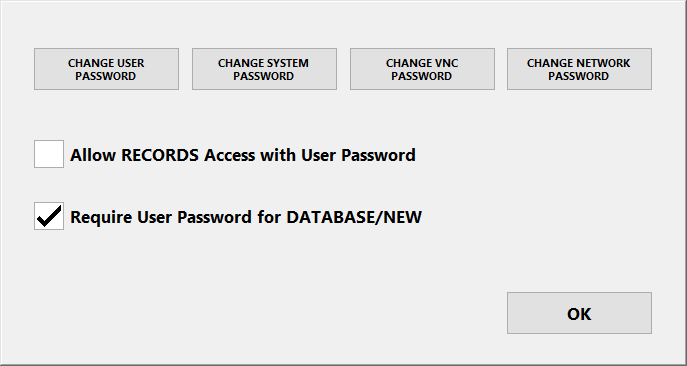
Figure 25 – operator console Password Settings dialog
| Setting | Description |
|---|---|
| Change User Password | Use this button to change the lower level ‘user’ password that can be used to access the Vehicle Database and Records screens.
This password should be given to users who need to add new vehicles to the database and view measurement records, but who should not be able to change system configuration. The default password is ‘TALLY’. |
| Change System Password | Use this button to change the ‘system’ password which allows access to all screens.
User configuration and system alignment settings cannot be modified without this password. The default password is ‘TALLY’. |
| Allow RECORDS access with User password | If enabled, the Records screen for reviewing measurement records is accessible with the ‘user’ password.
If this option is not enabled, the ‘system’ password is required to access the Records screen. |
| Require User password for DATABASE/NEW | If enabled, the ‘user’ password is required to access the Vehicle Database screen or to scan new vehicles into the database. No password is required if this is not enabled. |
Message board settings
The Message Board button in the System section of the Settings screen opens the Message Board Settings dialog (figure 26).
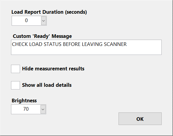
Figure 26 – operator console Message Board Settings dialog
| Setting | Description |
|---|---|
| Load Report Duration (seconds) | The number of seconds to display load reports before returning to ready state.
This can be set to allow truck drivers enough time to read load reports on the message board before the report is replaced with the ‘Ready’ message (READY TO SCAN). It is possible to scan the next vehicle while a load report is being displayed but no ‘Ready’ or ‘Proceed’ messages will be displayed before the load report time is up. Once a new scan starts however, the load report will be interrupted immediately by the ‘Scanning’ message. |
| Custom ‘Ready’ Message | Allows an optional user-defined scrolling text message to be displayed on the message board, below the standard ‘Ready’ message which displays when the MPS is ready to scan but no vehicle has been detected.
This enables custom information to be displayed to truck drivers. |
| Hide measurement results | Blanks out measured volumes on the message board so they cannot be read by truck drivers or casual observers.
Measurements are displayed on the operator console and printed tickets and recorded as normal. Use this option only where the measurement results are confidential. |
| Show all load details | If enabled, load detail data collected with each measurement is displayed on the message board along with the load report. |
| Brightness | Allows the sign brightness to be adjusted. |
Network settings
The MPS can be connected to wired and wireless computer networks for:
- remote access to measurement records and other user data
- remote-control and remote data entry.
Local network or internet connectivity may be required, depending on what MPS services need to be used.
An Ethernet port is provided at the rear of the operator console for wired connection to an office network, cellular router or user supplied networking equipment.
Additionally, an optional wireless radio may be fitted to the scan head and configured as an access point for connections from local wireless devices or as a client for long-distance wireless link to a remote network.
Ethernet port settings
The NETWORK (LAN) button in the System section of the Settings screen opens the Network Settings dialog (figure 27).
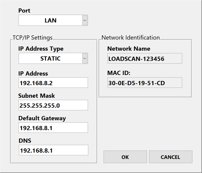
Figure 27 – operator console Network Settings dialog
| Setting | Description |
|---|---|
| Port | Set to LAN or WLAN to view or change settings for the corresponding Ethernet port.
The default is LAN, which corresponds to the wired Ethernet port on the operator console. If your LVS has a wireless radio fitted to the scan head, the WLAN option can be selected to configure TCP/IP settings for the operator console port on the wired side of the radio. In this case, suitable settings will depend on the wireless radio configuration. If the pre-configured WLAN port settings do not meet your requirements, contact Loadscan technical support before changing. |
| IP Address Type | By default, this is set to DHCP for automatic network settings on the LAN port.
To set a static IP address, change to STATIC and enter appropriate values for your network in the IP Address, Subnet Mask, Default Gateway and DNS fields. DHCP is not available for the WLAN port and cannot be set on the LAN port while a default gateway is configured on the WLAN port. |
| IP Address | IP address for the selected port in the format XXX.XXX.XXX.XXX.
This setting is read-only if IP Address Type is set to DHCP. |
| Subnet mask | Subnet mask for the selected port in the format XXX.XXX.XXX.XXX.
This setting is read-only if IP Address Type is set to DHCP. |
| Default Gateway | Default gateway for the selected port in the format XXX.XXX.XXX.XXX.
A default gateway can be set on LAN or WLAN but not both. This setting is read-only if IP Address Type is set to DHCP. |
| DNS | DNS server for the selected port in the format XXX.XXX.XXX.XXX. This setting is read-only if IP Address Type is set to DHCP. |
| Network Name | The network name (host name) of the operator console. This setting is read-only. |
| MAC ID | The MAC ID (physical address) of the selected port. Note that the MAC ID of the WLAN port is the physical address of the corresponding port on the operator console, not the connected wireless device. This setting is read-only. |
Contact your network administrator or Loadscan technical support if you need further assistance connecting to your network.
Network security settings
For improved IT security, incoming network connections using specific services and network ports can be blocked when not in use.
The Security button in the Network Settings dialog opens the Network Security dialog (figure 24).
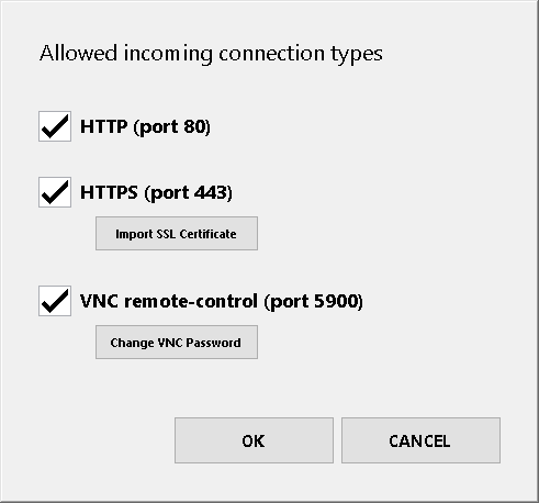
Figure 28 – operator console Network Security dialog
| Setting | Description |
|---|---|
| HTTP (port 80) | If enabled, incoming HTTP connections to active web services are possible on port 80.
If disabled, all incoming HTTP connections are blocked and port 80 is closed. This setting must be enabled for systems running LoadTrak™. |
| HTTPS (port 443) | If enabled, incoming secure HTTP connections to active web services are possible on port 443.
If disabled, all incoming secure HTTP connections are blocked and port 443 is closed. |
| IMPORT SSL CERTIFICATE | To allow validation of secure HTTP connections you can import an HTTPS certificate and key pair for your network domain. To do this:
|
| VNC remote-control (port 5900) | If enabled, Virtual Network Computing (VNC) clients can connect to the MPS on port 5900 to remote-control the MPS user interface. If disabled, the VNC service is not available and port 5900 is closed. |
| Change VNC Password | Change the password for remote-control of the MPS operator console from network connected Virtual Network Computing (VNC) clients. The default password is ‘TALLY’. Contact your Loadscan representative for more information about remote-control options. |
MPS remote-control via the MyScanner™ web service is not blocked by disabling incoming HTTP, HTTPS or VNC remote-control connections as it uses an outgoing HTTPS connection from the MPS to the MyScanner web server.
MyScanner remote-control can be blocked by disabling it in MyScanner settings as below.
MyScanner web service settings
The MyScanner button in the System section of the Settings screen opens the MyScanner Settings dialog (figure 29).
The MyScanner™ web service provides secure, cloud-based access to MPS systems and data. It includes functionality to:
- view, edit and export measurement records
- remotely control MPS systems
- view 3D scan profiles for advanced load profiling
- backup MPS data and synchronize multiple MPS systems
- view images/video for manual scan reviews (if LoadVision™ camera installed)
- view license plate images for vehicle identification auditing (if LPR camera(s) installed for automatic vehicle identification).
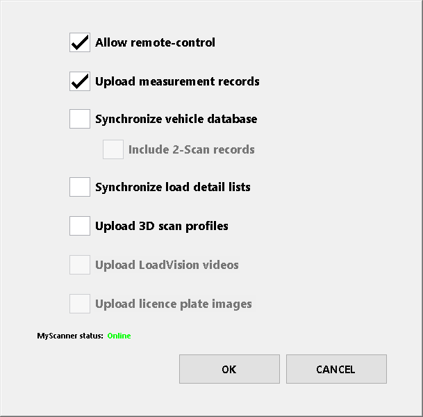
Figure 29 – operator console MyScanner Settings dialog
An internet connection to the MPS operator console and an active MyScanner account are required.
| Setting | Description |
|---|---|
| Allow remote-control | Enables/disables web based MPS remote-control via the MyScanner web portal. MyScanner remote-control makes it possible to remotely control the MPS user interface from anywhere with an internet connection and facilitates remote connections by Loadscan Technical Support. |
| Upload measurement records | Enables/disables automatic upload of measurement records to the MyScanner web server for real-time backup and remote access to measurement data. Users can log onto the MyScanner web portal to manually view, edit and export measurement records. |
| Synchronize vehicle database | If enabled, the MPS vehicle database is synchronized with an online database linked to your MyScanner account.
This can be used:
If the same trucks visit multiple MPS sites, this avoids the need to perform empty reference scans of the same truck at each site. |
| Synchronize load detail lists | If enabled, the selection lists for configured load detail prompts will be synchronized with online lists linked to your MyScanner account.
This can be used:
If the same load details need to be collected at each MPS, this can avoid maintaining separate lists at each site. Do not enable this option for multiple MPS systems connected to the same MyScanner account (organization) if lists need to be different at each site |
| Upload 3D scan profiles | If enabled, a 3D scan profile is uploaded to the MyScanner web server for every scan that appears in the measurement records. 3D scan profiles can be viewed in MyScanner. This facilitates visual inspection for:
|
| Upload LoadVision videos* |
If enabled, video/image files are uploaded to the MyScanner web server for every scan that appears in the measurement records.
Video and snapshot images can be viewed in MyScanner. This facilitates greater ability to review and audit measurement scans. *Only available if a LoadVision™ camera is installed. |
| Upload license plate images* | If enabled, images of detected licence plates are uploaded to the MyScanner web server for every scan that appears in the measurement records.
*Only available if LPR camera(s) are installed for automatic vehicle identification. |
| MyScanner status | Indicates whether the MPS has an authenticated connection to the MyScanner web server.
Online: the MPS has an authenticated connection to MyScanner. |
Contact your Loadscan representative for more information on the MyScanner™ web service and internet connection options.
2-Scan measurement settings
The 2-Scan button in the General Operation section of the Settings screen opens the 2-Scan Measurement Settings dialog (figure 30).
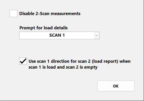
Figure 30 – operator console 2-Scan Measurement Settings dialog
| Setting | Description |
|---|---|
| Disable 2-Scan measurements | Can be used to disable 2-Scan mode.
When disabled, the system will not prompt for a 2-Scan measurement when a vehicle ID not in the vehicle database is entered at a vehicle ID prompt after a scan. |
| Prompt for load details | Set to SCAN 1 or SCAN 2 to control whether configured load detail prompts are shown after the first or second scan in 2-Scan mode. Generally, if trucks arrive on site loaded for the first scan, load details should be collected on the first scan.If trucks arrive empty for the first scan and pick up a load on site before the second scan, load details should be collected on the second scan. |
| Use scan 1 direction for scan 2 (load report) when scan 1 is load and scan 2 is empty | In 2-Scan mode the load is not measured and reported until the second scan. If the first scan is loaded, the second scan empty and the scans are performed in opposite directions then the desired ‘load direction’ is probably the direction of the first scan, not the second.
In this case, enable Use scan 1 direction for scan 2 (load report) when scan 1 is load and scan 2 is empty to use the scan direction of the first scan as the reported direction for the load report. This rule is applied regardless of the physical direction of the second scan, but only in the case where the first scan is the load scan and the second scan is the empty scan. |
Keypad beep
If Keypad beep is enabled, the operator console will produce a regular beep tone when the on-screen keypad is displayed and requires manual input.
The beep will not start until the keypad has been visible for 10 seconds and no input received.
Dialog timeout
The Dialog Timeout (seconds) selector controls the timeout for on-screen prompts and for cancelling a measurement record if this option is enabled.
By default, on-screen keypad prompts for vehicle ID and load detail entry timeout after 3 minutes (180 seconds).
If vehicle IDs are not entered in that time, the scan is cancelled.
If load details are not entered, they are set to ‘not entered’ in measurement records.
Increasing the timeout allows more time for data entry.
Decreasing the timeout reduces the time before the system returns to READY state and the next truck can be scanned (when no data is input).
Custom settings
Custom functions to meet application-specific requirements may be activated on the MPS.
Use the Custom button in the System section of the Settings screen to open the Custom Settings dialog (figure 34) to edit any activated custom setting parameters.
If no custom functionality is enabled, the CUSTOM button is disabled and greyed-out.
To edit custom settings:
- Select (highlight) the desired setting parameter as illustrated in figure 31.
- Use the Edit button to open the on-screen keypad.
- Enter the required value with reference to documentation for the related custom function.
For some settings a list of options is provided. For other settings free text entry is required.
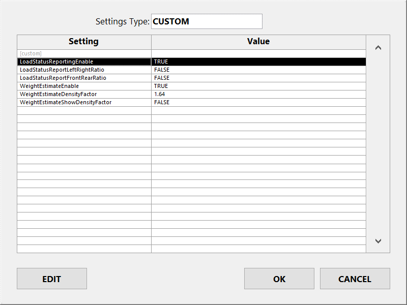
Figure 31 – operator console Custom Settings dialog
The following custom functions are pre-activated on the MPS, but functionality is disabled by default. Custom settings are available to enable and configure these functions:
| Common custom functions | Description |
|---|---|
| Load status reporting | Reports additional load quantity and load distribution status values for every measured load. These status values indicate if the load is underloaded, overloaded of unevenly loaded in the bin. |
| Weight Estimate | Estimates weight in tons/tonnes from product-specific density values for each measured load and reports as additional load details. |
Other common custom functions available for activation on the MPS include:
| Common custom functions | Description |
|---|---|
| LoadTrak™ | LoadTrak is an add-on product for the MPS system. LoadTrak in-cab consoles provide MPS remote data entry and reporting functionality for truck drivers. |
| LoadSync API™ | Allows measurement records to be retrieved from the MPS via a JSON web API. |
| LoadSync SQL™ | Pushes measurement records from the MPS to an external SQL database via local network connection. |
Custom functions can only be activated by Loadscan and except for pre-activated functions included with the MPS, are documented separately.
If you are interested in adding custom functionality to your MPS system, contact your Loadscan representative to discuss the possibilities.
In this Article
The Settings screen (figure 19) provides options for customising the MPS configuration.
Access this screen from the SETTINGS button on the Main screen. The ‘system’ password is required.

Figure 19 – operator console Settings screen
General operation settings
The General Operation section of the Settings screen provides options for:
- vehicles entering or leaving the site (See Defining ‘in’ and ‘out’ scan directions.)
- general options that apply for both scan directions.
If all direction specific options are disabled for one scan direction, scanning is disabled in that direction. This may be desirable where the LVS is used in only one direction but vehicles need to pass through the scan area in both directions.
Empty reference scans can always be performed in either direction.
| Setting | Description |
|---|---|
| Load Thresholds | Opens the Load Thresholds dialog to set load status reporting thresholds.
This button is only visible if load status reporting is enabled. |
| Compute load | Enable/disable load measurement for the corresponding scan direction. |
| Log all errors if ID known | Enable/disable error logging for the corresponding scan direction. When enabled, scans where the target vehicle(s) is identified by ID tag but no measurement result is reported because of errors, will be logged to file. A record of the vehicle trip for a failed scan is created, without measurement data. This function is typically used to record the time, date and vehicle ID(s) for failed scans where all vehicles have ID tags fitted and do not stop after scanning (no load details prompts).If this option is disabled then error scans that do not result in a load measurement will not be recorded. If Log all errors if ID known is enabled and Compute load is disabled, vehicles with ID tags will be recorded, but marked as TRACKING ONLY (i.e. without measurement data). |
| Site name | The site name appears at the top of the Main screen, on printed tickets and in measurement records. |
| Allow cancel / modify record | If enabled, a scan record can be cancelled or load details modified up to two minutes after a new load report.
See Cancel/Modify record. |
| Allow pre-scan data entry | If enabled, vehicle IDs and any configured load details can be pre-entered before performing a scan instead of after the scan. See Pre-scan data entry. |
| Vehicle identification | This selector allows the method of vehicle identification to be set:
|
Configuring load detail prompts
User-defined load details can be configured to record the load material, source, destination, or such like, together with measurement records.
To add or edit load detail prompts, use the Load Details button in the General Operation section of the Settings screen.
This displays the Load Details dialog (figure 20).

Figure 20 – operator console Load Details dialog
| Setting | Description |
|---|---|
| Prompt for Load Details | If enabled, the system prompts for keypad entry/selection of user-defined load details after every scan, before reporting and recording measurement data.
A basic load report is displayed on the message board while load detail prompts appear on the operator console screen after a scan. A load report will not appear on the operator console screen until all load details have been entered. A maximum of six user-defined load details can be created. |
| Skip for Tracking-Only | If enabled, load detail prompts will be skipped for tracking-only vehicle scans. (See Tracking only (no measurement).) |
| Load Details | The current list of user-defined load details in the order they will be prompted and recorded. Use this selector to select a specific load detail to edit or remove. |
| Add | Add a new user-defined load detail after any existing ones. (See Load detail properties below.) |
| Edit | Edit the selected load detail. (See Load detail properties below.) |
| Remove | Remove the selected load detail. |
| AUTO RESPONSES | Open the Auto-Responses dialog where automatic responses to load detail prompts can be set for selected vehicles. (See Automatic responses to load detail prompts.) |
Load detail properties
The Load Detail Properties dialog (figure 21) opens when a load detail is added or edited.

Fig 21 – operator console Load Detail Properties dialog
| Setting | Description |
|---|---|
| Detail type |
|
| Name | The name to assign to the load detail. The name should match the detail to be requested, such as ‘Load Source’, ‘Load Destination’ or ‘Driver’. |
| Use list | Enable/disable list selection on the load detail prompt. (See Load detail selection lists below.) |
| Require list match | If enabled, the text entered must exactly match one of the list items. If not enabled, any text can be entered. If Require list match is enabled and the selection list has only one item, that item is selected automatically without prompting. |
| Allow blank | If enabled, it is possible to close the prompt without entering any text. |
Load detail selection lists
For each configured load detail, it is possible to display a predefined selection list with the keypad prompt for quick and accurate text entry.
To create or update a selection list for a configured load detail:
- Select the load detail on the Load Details dialog (figure 20).
- Push the Edit button to open the Load Detail Properties dialog (figure 21).
- Push the List button to open the List dialog (figure 22).

Fig 22 – operator console List dialog
Use the horizontal scrollbar to view hidden fields.
| Setting/button | Description |
|---|---|
| Add | Add a list item. (See List item fields below.)
If an existing list item is selected, the new item is inserted immediately before the selection. If no item is selected, the new item is appended to the end of the list. List item order is only important if using selection dependent list filters. (See the supplementary support document Loadscan LVS – Advanced Load Detail Options.) Lists are alphanumerically sorted for load detail selection. |
| Edit | Edit the selected list item. (See List item fields below.) |
| Remove | Remove the selected list item. |
| Import | Import a predefined list file from USB flash drive. The list can be created in advance on an office computer. (See How to generate and import a load detail selection list file below.) |
| Export | Export the list to file on USB flash drive for external editing, transfer to another MPS or backup. |
List item fields
The List Item dialog (figure 23) opens when a list item is added or edited.

Figure 23 – operator console List Item dialog
Each list item has at least the following three fields:
| Field | Description |
|---|---|
| Name | The item name as it appears in the selection list. This field is required. |
| Value | The value that is output when name is selected. This is the text value that is shown on load reports and saved in measurement records. If not set, value will be the same as name. It may be desirable to output a different value than the name displayed on the selection list. For example, abbreviations or nicknames for selection and full names on load reports and measurement records. |
| Custom | An optional user-defined property associated with the list item and saved with measurement records. This can be for example, a ‘material code’ associated with a material name and required by external systems that process MPS measurement records. |
Additional fields may be present, depending on the load detail type. These are only required for specific custom functions and usage is detailed in the associated documentation.
For example, the ‘Density’ field present for the ‘Material (product type)’ load detail type is used for the weight estimate function. (See Weight estimate function.)
Refer to the supplementary support document Loadscan LVS – Advanced Load Detail Options for example usage of value and custom fields and additional advanced list functionality
How to generate and import a load detail selection list file
- Lists can be created in Microsoft® Notepad or a similar text editor:
1. Create the list as a text file with each item name on a new line.
If additional fields are required, add these after names with commas between fields, in the order they appear on the List Item dialog (figure 23).
Fields that are not required can be left blank (skip with comma only) and no fields after the last required field need to be entered.
Do not include commas in the text values.
1. Copy the list file to a USB flash drive with a file name that matches the load detail name. For example, if the load detail is “Product” the file name must be “Product.txt”.
2. Insert the USB drive into the operator console USB port and push the Import button on the List dialog.
If the import is successful, the list items will appear in the list display.
Defining ‘in’ and ‘out’ scan directions
Toggle the button below the Direction image in the System section of the Settings screen to match the direction of the truck shown, relative to the pictured scan head and corresponding to the actual direction for the installed MPS.
Time and date settings
The Time/Date button in the System section of the Settings screen opens the Time and Date dialog (figure 24) for setting the current time, date and time zone.
If the operator console is connected to a local network with internet access or a local NTP time server, the system time can be adjusted automatically.
When Adjust time automatically is enabled, the system will synchronize time with the time server specified in NTP Server.

Figure 24 – operator console Time and Date dialog
If the operator console is connected to a local network with internet access or a local NTP time server, the system time can be adjusted automatically.
When Adjust time automatically is enabled, the system will synchronize time with the time server specified in NTP Server.
The NTP server can be specified by DNS name or IP address.
Time/Date can be adjusted manually only when automatic time adjustment is disabled.
Set Time Zone to match the region where your MPS is installed.
Note that time is displayed in 24-hour format and abbreviated, language-specific month names are used for on-screen date displays and on printed tickets.
Date and time are written to measurement record log files in the following ISO 8601 compliant format:
YYYY-MM-DD HH:MM:SS±hh:mm
Where ±hh:mm is the timezone offset from Universal Time (UTC).
This format provides compatibility for importing measurement records into databases and other software systems and is a widely accepted international format.
The current time is displayed at the top left of the operator console Main screen.
Language setting
If alternative languages or regional variants are installed for the MPS software, then the Language selector in the System section of the Settings screen can be used to switch between installed languages/regions.
The system must be re-started for language or region changes to take effect.
Password settings
The PASSWORDS button in the System section of the Settings screen opens the Password Settings dialog (figure 25).

Figure 25 – operator console Password Settings dialog
| Setting | Description |
|---|---|
| Change User Password | Use this button to change the lower level ‘user’ password that can be used to access the Vehicle Database and Records screens.
This password should be given to users who need to add new vehicles to the database and view measurement records, but who should not be able to change system configuration. The default password is ‘TALLY’. |
| Change System Password | Use this button to change the ‘system’ password which allows access to all screens.
User configuration and system alignment settings cannot be modified without this password. The default password is ‘TALLY’. |
| Allow RECORDS access with User password | If enabled, the Records screen for reviewing measurement records is accessible with the ‘user’ password.
If this option is not enabled, the ‘system’ password is required to access the Records screen. |
| Require User password for DATABASE/NEW | If enabled, the ‘user’ password is required to access the Vehicle Database screen or to scan new vehicles into the database. No password is required if this is not enabled. |
Message board settings
The Message Board button in the System section of the Settings screen opens the Message Board Settings dialog (figure 26).

Figure 26 – operator console Message Board Settings dialog
| Setting | Description |
|---|---|
| Load Report Duration (seconds) | The number of seconds to display load reports before returning to ready state.
This can be set to allow truck drivers enough time to read load reports on the message board before the report is replaced with the ‘Ready’ message (READY TO SCAN). It is possible to scan the next vehicle while a load report is being displayed but no ‘Ready’ or ‘Proceed’ messages will be displayed before the load report time is up. Once a new scan starts however, the load report will be interrupted immediately by the ‘Scanning’ message. |
| Custom ‘Ready’ Message | Allows an optional user-defined scrolling text message to be displayed on the message board, below the standard ‘Ready’ message which displays when the MPS is ready to scan but no vehicle has been detected.
This enables custom information to be displayed to truck drivers. |
| Hide measurement results | Blanks out measured volumes on the message board so they cannot be read by truck drivers or casual observers.
Measurements are displayed on the operator console and printed tickets and recorded as normal. Use this option only where the measurement results are confidential. |
| Show all load details | If enabled, load detail data collected with each measurement is displayed on the message board along with the load report. |
| Brightness | Allows the sign brightness to be adjusted. |
Network settings
The MPS can be connected to wired and wireless computer networks for:
- remote access to measurement records and other user data
- remote-control and remote data entry.
Local network or internet connectivity may be required, depending on what MPS services need to be used.
An Ethernet port is provided at the rear of the operator console for wired connection to an office network, cellular router or user supplied networking equipment.
Additionally, an optional wireless radio may be fitted to the scan head and configured as an access point for connections from local wireless devices or as a client for long-distance wireless link to a remote network.
Ethernet port settings
The NETWORK (LAN) button in the System section of the Settings screen opens the Network Settings dialog (figure 27).

Figure 27 – operator console Network Settings dialog
| Setting | Description |
|---|---|
| Port | Set to LAN or WLAN to view or change settings for the corresponding Ethernet port.
The default is LAN, which corresponds to the wired Ethernet port on the operator console. If your LVS has a wireless radio fitted to the scan head, the WLAN option can be selected to configure TCP/IP settings for the operator console port on the wired side of the radio. In this case, suitable settings will depend on the wireless radio configuration. If the pre-configured WLAN port settings do not meet your requirements, contact Loadscan technical support before changing. |
| IP Address Type | By default, this is set to DHCP for automatic network settings on the LAN port.
To set a static IP address, change to STATIC and enter appropriate values for your network in the IP Address, Subnet Mask, Default Gateway and DNS fields. DHCP is not available for the WLAN port and cannot be set on the LAN port while a default gateway is configured on the WLAN port. |
| IP Address | IP address for the selected port in the format XXX.XXX.XXX.XXX.
This setting is read-only if IP Address Type is set to DHCP. |
| Subnet mask | Subnet mask for the selected port in the format XXX.XXX.XXX.XXX.
This setting is read-only if IP Address Type is set to DHCP. |
| Default Gateway | Default gateway for the selected port in the format XXX.XXX.XXX.XXX.
A default gateway can be set on LAN or WLAN but not both. This setting is read-only if IP Address Type is set to DHCP. |
| DNS | DNS server for the selected port in the format XXX.XXX.XXX.XXX. This setting is read-only if IP Address Type is set to DHCP. |
| Network Name | The network name (host name) of the operator console. This setting is read-only. |
| MAC ID | The MAC ID (physical address) of the selected port. Note that the MAC ID of the WLAN port is the physical address of the corresponding port on the operator console, not the connected wireless device. This setting is read-only. |
Contact your network administrator or Loadscan technical support if you need further assistance connecting to your network.
Network security settings
For improved IT security, incoming network connections using specific services and network ports can be blocked when not in use.
The Security button in the Network Settings dialog opens the Network Security dialog (figure 24).

Figure 28 – operator console Network Security dialog
| Setting | Description |
|---|---|
| HTTP (port 80) | If enabled, incoming HTTP connections to active web services are possible on port 80.
If disabled, all incoming HTTP connections are blocked and port 80 is closed. This setting must be enabled for systems running LoadTrak™. |
| HTTPS (port 443) | If enabled, incoming secure HTTP connections to active web services are possible on port 443.
If disabled, all incoming secure HTTP connections are blocked and port 443 is closed. |
| IMPORT SSL CERTIFICATE | To allow validation of secure HTTP connections you can import an HTTPS certificate and key pair for your network domain. To do this:
|
| VNC remote-control (port 5900) | If enabled, Virtual Network Computing (VNC) clients can connect to the MPS on port 5900 to remote-control the MPS user interface. If disabled, the VNC service is not available and port 5900 is closed. |
| Change VNC Password | Change the password for remote-control of the MPS operator console from network connected Virtual Network Computing (VNC) clients. The default password is ‘TALLY’. Contact your Loadscan representative for more information about remote-control options. |
MPS remote-control via the MyScanner™ web service is not blocked by disabling incoming HTTP, HTTPS or VNC remote-control connections as it uses an outgoing HTTPS connection from the MPS to the MyScanner web server.
MyScanner remote-control can be blocked by disabling it in MyScanner settings as below.
MyScanner web service settings
The MyScanner button in the System section of the Settings screen opens the MyScanner Settings dialog (figure 29).
The MyScanner™ web service provides secure, cloud-based access to MPS systems and data. It includes functionality to:
- view, edit and export measurement records
- remotely control MPS systems
- view 3D scan profiles for advanced load profiling
- backup MPS data and synchronize multiple MPS systems
- view images/video for manual scan reviews (if LoadVision™ camera installed)
- view license plate images for vehicle identification auditing (if LPR camera(s) installed for automatic vehicle identification).

Figure 29 – operator console MyScanner Settings dialog
An internet connection to the MPS operator console and an active MyScanner account are required.
| Setting | Description |
|---|---|
| Allow remote-control | Enables/disables web based MPS remote-control via the MyScanner web portal. MyScanner remote-control makes it possible to remotely control the MPS user interface from anywhere with an internet connection and facilitates remote connections by Loadscan Technical Support. |
| Upload measurement records | Enables/disables automatic upload of measurement records to the MyScanner web server for real-time backup and remote access to measurement data. Users can log onto the MyScanner web portal to manually view, edit and export measurement records. |
| Synchronize vehicle database | If enabled, the MPS vehicle database is synchronized with an online database linked to your MyScanner account.
This can be used:
If the same trucks visit multiple MPS sites, this avoids the need to perform empty reference scans of the same truck at each site. |
| Synchronize load detail lists | If enabled, the selection lists for configured load detail prompts will be synchronized with online lists linked to your MyScanner account.
This can be used:
If the same load details need to be collected at each MPS, this can avoid maintaining separate lists at each site. Do not enable this option for multiple MPS systems connected to the same MyScanner account (organization) if lists need to be different at each site |
| Upload 3D scan profiles | If enabled, a 3D scan profile is uploaded to the MyScanner web server for every scan that appears in the measurement records. 3D scan profiles can be viewed in MyScanner. This facilitates visual inspection for:
|
| Upload LoadVision videos* |
If enabled, video/image files are uploaded to the MyScanner web server for every scan that appears in the measurement records.
Video and snapshot images can be viewed in MyScanner. This facilitates greater ability to review and audit measurement scans. *Only available if a LoadVision™ camera is installed. |
| Upload license plate images* | If enabled, images of detected licence plates are uploaded to the MyScanner web server for every scan that appears in the measurement records.
*Only available if LPR camera(s) are installed for automatic vehicle identification. |
| MyScanner status | Indicates whether the MPS has an authenticated connection to the MyScanner web server.
Online: the MPS has an authenticated connection to MyScanner. |
Contact your Loadscan representative for more information on the MyScanner™ web service and internet connection options.
2-Scan measurement settings
The 2-Scan button in the General Operation section of the Settings screen opens the 2-Scan Measurement Settings dialog (figure 30).

Figure 30 – operator console 2-Scan Measurement Settings dialog
| Setting | Description |
|---|---|
| Disable 2-Scan measurements | Can be used to disable 2-Scan mode.
When disabled, the system will not prompt for a 2-Scan measurement when a vehicle ID not in the vehicle database is entered at a vehicle ID prompt after a scan. |
| Prompt for load details | Set to SCAN 1 or SCAN 2 to control whether configured load detail prompts are shown after the first or second scan in 2-Scan mode. Generally, if trucks arrive on site loaded for the first scan, load details should be collected on the first scan.If trucks arrive empty for the first scan and pick up a load on site before the second scan, load details should be collected on the second scan. |
| Use scan 1 direction for scan 2 (load report) when scan 1 is load and scan 2 is empty | In 2-Scan mode the load is not measured and reported until the second scan. If the first scan is loaded, the second scan empty and the scans are performed in opposite directions then the desired ‘load direction’ is probably the direction of the first scan, not the second.
In this case, enable Use scan 1 direction for scan 2 (load report) when scan 1 is load and scan 2 is empty to use the scan direction of the first scan as the reported direction for the load report. This rule is applied regardless of the physical direction of the second scan, but only in the case where the first scan is the load scan and the second scan is the empty scan. |
Keypad beep
If Keypad beep is enabled, the operator console will produce a regular beep tone when the on-screen keypad is displayed and requires manual input.
The beep will not start until the keypad has been visible for 10 seconds and no input received.
Dialog timeout
The Dialog Timeout (seconds) selector controls the timeout for on-screen prompts and for cancelling a measurement record if this option is enabled.
By default, on-screen keypad prompts for vehicle ID and load detail entry timeout after 3 minutes (180 seconds).
If vehicle IDs are not entered in that time, the scan is cancelled.
If load details are not entered, they are set to ‘not entered’ in measurement records.
Increasing the timeout allows more time for data entry.
Decreasing the timeout reduces the time before the system returns to READY state and the next truck can be scanned (when no data is input).
Custom settings
Custom functions to meet application-specific requirements may be activated on the MPS.
Use the Custom button in the System section of the Settings screen to open the Custom Settings dialog (figure 34) to edit any activated custom setting parameters.
If no custom functionality is enabled, the CUSTOM button is disabled and greyed-out.
To edit custom settings:
- Select (highlight) the desired setting parameter as illustrated in figure 31.
- Use the Edit button to open the on-screen keypad.
- Enter the required value with reference to documentation for the related custom function.
For some settings a list of options is provided. For other settings free text entry is required.

Figure 31 – operator console Custom Settings dialog
The following custom functions are pre-activated on the MPS, but functionality is disabled by default. Custom settings are available to enable and configure these functions:
| Common custom functions | Description |
|---|---|
| Load status reporting | Reports additional load quantity and load distribution status values for every measured load. These status values indicate if the load is underloaded, overloaded of unevenly loaded in the bin. |
| Weight Estimate | Estimates weight in tons/tonnes from product-specific density values for each measured load and reports as additional load details. |
Other common custom functions available for activation on the MPS include:
| Common custom functions | Description |
|---|---|
| LoadTrak™ | LoadTrak is an add-on product for the MPS system. LoadTrak in-cab consoles provide MPS remote data entry and reporting functionality for truck drivers. |
| LoadSync API™ | Allows measurement records to be retrieved from the MPS via a JSON web API. |
| LoadSync SQL™ | Pushes measurement records from the MPS to an external SQL database via local network connection. |
Custom functions can only be activated by Loadscan and except for pre-activated functions included with the MPS, are documented separately.
If you are interested in adding custom functionality to your MPS system, contact your Loadscan representative to discuss the possibilities.
